I am looking for help with a project. I am very new here so please excuse my ignorance, and please be kind.
Using the Blynk app, I would like to control the on, off, and dimmer functions of the 12v lights in my RV. My thought is to install a Wemos mini and transistor under the light in the fixture.
I would like the existing wall switch that currently controls the lights, to override all of the functions of the Wemos and act as a regular light switch, as if there was not a Wemos installed; this is where I am needing help.
I currently have the Wemos clone switching the transistor on/off and dimming a light using the phone app on my breadboard, working great–pretty simple. I am stuck at adding the wall switch into the equation as an override.
Again I am very new to this, I just picked up these parts and starting playing with them over the weekend. Any help would be appreciated! Thank you in advance!
Not easy to achieve, and complicated by the mobile nature of the project - which I assume can mean times without internet connectivity.
The first part of the process needs you to change the wiring to the light switch, so that instead of switching the power it pulls one pin of the Wemos HIGH or LOW (note that this is 3.3v/5v logic level, NOT 12v levels which will kill your Wemos).
Your Wemos then need to be running 24/7 to respond to this change of state and switch the lights, so you’ll need to live with the power drain that goes with this.
You’ll then need to write your code so that it works regardless of whether you have a WiFi and Internet connection.
You bring up some very good points! I am also cognizant of these challenges and do not possess the knowledge to overcome them all, yet.
The suggestion of converting the switch to logic level voltage makes a lot of sense. However, for the constant power consumption, I was thinking to wire the switch so that in the off position, it would kill all power. In the on position, it would act as an on/auto, or on/remote control–powering the wemos only when the switch is on. After a year of full-time RVing, I have yet to hit below 80% on my battery reserves, however, there may be times I wish to shut it all down to conserve energy.
Being very new to coding, Arduino IDE, Blynk, etc, I am wondering if the best way to accomplish the above is to maybe have the light wired to an NC relay that is powered by the switch; having the relay controlled by the wemos, that is also powered by the switch?
I am also concerned about the need for a consistent internet connection. I assume it is possible to use Blynk on a private server, am I wrong? Also, if it is possible, can someone point me in the direction of a forum or faq about this?
Thank you again, the suggestions are appreciated and helpful!
I cant visualise this setup. Do you have a schematic?
Yes, a local server is possible. Most people use a Raspberry Pi for this - but that’s another thing to power!
Info on how to set-up and maintain a local server is here… https://github.com/blynkkk/blynk-server
plus there are many topics on the subject on this forum.
I built a similar setup for my camper van but instead of using the stock wall switch I used a push-button rotary encoder. With the rotary encoder you can have a manual method for turning on/dimming the lights and have it synced with your blynk virtual controls. I can post the arduino sketch if you need it.
These are the rotary encoders I used:
(https://smile.amazon.com/gp/product/B06XQTHDRR/ref=ppx_yo_dt_b_asin_title_o06_s00?ie=UTF8&psc=1)
That’s awesome, thanks! Yes, please share your sketch! One of the problems I am having is that I only have access to the positive wires of the light at the switch–no light grounds. I was going to try and build a high-side led dimmer like this one:
Does your setup need access to the negative leg of the light to work?
You should always have a ground point on your circuit. Any metal point on your vehicle should work.Code for using the KY-040 push button rotary encoder synced with blynk.
    #define BLYNK_PRINT Serial    // Comment this out to disable prints and save space
    //#define BLYNK_DEBUG // optional, this enables more detailed prints
    #include <ESP8266WiFi.h>
    #include <ArduinoOTA.h>
    #include <WiFiUdp.h>
    //#include <WiFiClient.h>
    #include <BlynkSimpleEsp8266.h>
    /*
    V0 - virtual button to power on and off light
    V1 - sends millis()/1000 and displays on the Blynk App
    V2 - slider on blynk
    V5 - Tweet LED on blynk

    Following are for the bed script
    V9 - Virtual Button0
    V10 - Virtual Button1
    V11 - sends millis()/1000 and displays on the Blynk App
    */
    bool somethingchanged = false; //Used to limit the blynk calls to only when necessary
    bool runonce = true; //after everything starts (wifi, blynk, OTA) run a command to turn light off and dimmer to medium

    // Rotary Encoder Inputs
    //#define CLK 2 //Pin A
    //#define DT 3  //Pin B
    //#define SW 5  //Pin 3 - push switch
    const int CLK = D2;
    const int DT = D3;
    const int SW = D5;
    int counter = 0;
    int lastcount = 0;
    int currentStateCLK;
    int lastStateCLK;
    String currentDir ="";
    unsigned long lastButtonPress = 0;

    //LED
    int LEDpin = D1;
    int LEDbright = 700; //maximum value for dimmer 1023 - make sure virtual slider has same min and max
    const int LEDmin = 20; // minimum value for dimmer - make sure virtual slider in blynk has same min and max
    bool LEDstate = false;

    //BLYNK INPUTS
    char auth[] = "youruniqueauthgoeshere";
    BlynkTimer Timer;

    // Your WiFi credentials.
    // Set password to "" for open networks.
    char ssid[] = "yourWIFISSID";
    const char* ssid1 = "yourWIFISSID"; // can't remember why I did two network entries but it worked - I'll delve into it later
    char pass[] = "yourWIFIpassword";
    const char* password1 = "yourWIFIpassword";

    void setup() {

      // Set encoder pins as inputs
      pinMode(CLK,INPUT);
      pinMode(DT,INPUT);
      pinMode(SW, INPUT_PULLUP);

      pinMode(LEDpin, OUTPUT);
      // blink lights once to indicate program has started
      analogWrite(LEDpin, LEDbright);
      delay(1000);
      analogWrite(LEDpin, 0); //was power - Note that on the ESP2866 you have to analogWrite a value of 0 to use digitalWrite
      //digitalWrite(power, LOW); //This forces the default state on start0, LOW or FALSE or 0 (off)
      delay(100);

      // Setup Serial Monitor
      Serial.begin(9600);
      delay(10);
      Serial.println("Starting ...");

      // Read the initial state of CLK
      lastStateCLK = digitalRead(CLK);

      Blynk.begin(auth, ssid, pass);  //connects to the blynk server using the credentals from above.
      //Blynk.config(auth, server, port);
      //Blynk.connect();
      Serial.println("\n");
      Serial.println("Blynk Started...\n");

      //Blynk.syncAll(); //this causes serial monitor to stop outputting after "OTA". Never gets to "OTA Starting..."

      //Start wifi or OTA won't work
      WiFi.mode(WIFI_STA);
      WiFi.begin(ssid1, password1);
      while (WiFi.waitForConnectResult() != WL_CONNECTED) {
        Serial.println("Connection Failed! Rebooting...");
        delay(5000);
        ESP.restart();
      }
      // Hostname defaults to esp8266-[ChipID]
      ArduinoOTA.setHostname("Blynk-Wemos-Light1");

      Serial.println("OTA Starting...\n");
      ArduinoOTA.onStart([]() {
        Serial.println("Start");
      });
      ArduinoOTA.onEnd([]() {
        Serial.println("\nEnd");
      });
      ArduinoOTA.onProgress([](unsigned int progress, unsigned int total) {
        Serial.printf("Progress: %u%%\r", (progress / (total / 100)));
      });
      ArduinoOTA.onError([](ota_error_t error) {
        Serial.printf("Error[%u]: ", error);
        if (error == OTA_AUTH_ERROR) Serial.println("Auth Failed");
        else if (error == OTA_BEGIN_ERROR) Serial.println("Begin Failed");
        else if (error == OTA_CONNECT_ERROR) Serial.println("Connect Failed");
        else if (error == OTA_RECEIVE_ERROR) Serial.println("Receive Failed");
        else if (error == OTA_END_ERROR) Serial.println("End Failed");
      });
      ArduinoOTA.begin();
      Serial.println("Ready");
      Serial.print("IP address: ");
      Serial.println(WiFi.localIP());
      Timer.setInterval(500L, timerevent); //calls the function timerevent every mils seconds (i.e. 1000L = 1 sec)
      Blynk.syncVirtual(V0, V2);  //sync virtual button and slider to last values stored on blynk app
    }

    BLYNK_WRITE(V0) // Virtual Button to Monitor
    {
      somethingchanged = true;
      if (param.asInt() == 1){
        LEDstate = true;
        //Blynk.virtualWrite(V0, 1);
        //analogWrite(LEDpin, LEDbright);
        Serial.println("Blynk Button Pressed");
      }else{
        LEDstate = false;
        //analogWrite(LEDpin, 0);
        //Blynk.virtualWrite(V0, 0);
      }
    }

    BLYNK_WRITE(V2) // Virtual Slider to Monitor
    {
      somethingchanged = true;
      LEDbright = param.asInt();
    }

    void timerevent() //runs per interval as defined in setup() for Timer.setInterval
    {
      if (runonce){ // on a restart turn the light off and set dimmer value to something in the medium level
        runonce = not runonce;
        //LEDbright = 700; //syncVirtual command in setup sets the LEDbright to the last stored value in the app
        LEDstate = false;
        Blynk.virtualWrite(V0, 0);
        analogWrite(LEDpin, 0);
      }
      Blynk.virtualWrite(V1, millis() / 1000); // sends time since program start to blynk app every second
      if (somethingchanged){
        int countdif = lastcount - counter;
        //Takes about 20 turns on the physical knob so increment or decrement brightness by a value of 51 for each count
        LEDbright = LEDbright - countdif * 51;
       if (LEDbright > 1023){
          LEDbright = 1023;
          counter = 52; //keep the counter from going too far positive or you'll have to turn the knob back to the left that many more times
        }
        if (LEDbright < 0){
          LEDbright = LEDmin;
          counter = 0; //keep the counter from going negative or you'll have to turn the knob back to the right that many more times
        }
       Serial.print("LEDbright: ");
       Serial.println(LEDbright);
        if (LEDstate){
          Blynk.virtualWrite(V0, 1);
          analogWrite(LEDpin, LEDbright);
        } else {
          Blynk.virtualWrite(V0, 0);
          analogWrite(LEDpin, 0);
        }
        somethingchanged = false;
        lastcount = counter;
        Blynk.virtualWrite(V2, LEDbright);
      }
      //Blynk.syncVirtual(V0, V2);  //sync virtual buttons and slider
    }

    void loop() {
      Blynk.run();
      Timer.run();

      // Read the current state of CLK
      currentStateCLK = digitalRead(CLK);

      // If last and current state of CLK are different, then pulse occurred
      // React to only 1 state change to avoid double count
      if (currentStateCLK != lastStateCLK  && currentStateCLK == 1){

        // If the DT state is different than the CLK state then
        // the encoder is rotating CW so increment
        if (digitalRead(DT) != currentStateCLK) {
          counter ++;
          currentDir ="CW";
        } else {
          // Encoder is rotating CCW so decrement
          counter --;
          currentDir ="CCW";
        }
        somethingchanged = true;

        Serial.print("Direction: ");
        Serial.print(currentDir);
        Serial.print(" | Counter: ");
        Serial.println(counter);
      }

      // Remember last CLK state
      lastStateCLK = currentStateCLK;

      // Read the button state
      int btnState = digitalRead(SW);

      //If we detect LOW signal, button is pressed
      if (btnState == LOW) {
        //if 50ms have passed since last LOW pulse, it means that the
        //button has been pressed, released and pressed again
        if (millis() - lastButtonPress > 50) {
          Serial.println("Button pressed!");
          LEDstate = not LEDstate;
          somethingchanged = true;
        }

        // Remember last button press event
        lastButtonPress = millis();
      }

      // Put in a slight delay to help debounce the reading
      delay(1);
      ArduinoOTA.handle();
    }
Hello all,
I have made some progress, but need some more help!
I have an led dimmer working on my breadboard using an n-channel mosfet, Wemos D1 mini, and standard Blynk sketch–I just added a button and a slider in the Blynk app and it works great and dims the LED no problems.
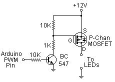
I am trying to control 10 LEDs that are in the ceiling of my RV, I can access the ground wires to the light, only at the fixtures so I cannot use the PWM of the n-channel mosfet, unless I have one at each light or run a new ground wire to the lights–not reasonable.
I do have access to all of the 12v power that is powering the lights from a single-pole switch. So, I transitioned to this setup (picture schematic included below) using a p-channel mosfet. It works, BUT, the LED is blinking/pulsing so bad that it is not usable as it is currently configured. I also tried a different bulb, no luck. Again, both bulbs worked fine using the n-channel mosfet.
Question, why is it blinking/pulsing so much? Can I change the pwm frequency in the Blynk app or sketch? Can I change the value of one of the resistors to make it more linear? Do I need to change the LEDs? What am I doing wrong? Thank you!
Thank you for sharing Hydro, I will try playing with this! I have access to a common ground. But I do not know if it is possible to PWM a common ground–I do not have access to the LED ground before it is grounded to the common vehicle ground, so I don’t think I can use an n-channel mosfet to PWM.
That seems a high component count just to dim a LED.
I’d probably use an RLB8721 N-Channel MOSFET driven directly from a GPIO pin on the NodeMCU. This tutorial refers to LED strips, but your setup is similar to one colour channel with a common ground.
Hello all, I need a bit more help:
I can control on/off and PWM. I rewired the existing 12v switch that was powering the lights to use logic level (3.3v) from the board (wemosmini) to control the on-off in parallel with the wemos/blynk-app. The problem is, I can control the lights fully remotely when the switch is off, but, when the switch is turned on it sorta acts as an override and turns the lights on ignoring the switch state in the Blynk app. For instance, the switch is off and the light is dimmed to 50% via the app when the switch is turned on (closed) it turns the lights on at 100%, when the switch is turned off (open) the lights return to the 50% brightness according to the Blynk app. I would prefer the switch overrides the app and vice versa so I could, for instance, turn the lights off even if the switch is on (closed). I know this is possible, but I am having a brain fart when trying to code it. Help is apreaited!
This is my current code:
#include <BlynkSimpleEsp8266.h
#include <ArduinoOTA.h

//WIFI-CRED
char auth[] = "XXXX";
char ssid[] = "XXXX";
char pass[] = "XXXX";
//END WIFI-CRED

//OTA-PASS
char hostOTA[] = "BedroomLts";
char passOTA[] = "XXXX";
//END OTA-PASS

//LIGHTSW-SETUP
int switchPin = D8;     //from single pole, logic-level-voltage switch
int ledPin =  D7;      // the number of the load pin used to drive relay
int switchState = 0;
//END LIGHTSW-SETUP

//RESET Function
BLYNK_WRITE(V10)
{
  if (param.asInt()) // If the button widget sent a "1" (on)
  {
      ESP.reset(); // Reset
  }
}
//END RESET Function

//-----------------------------
void setup()
{
//SWITCH
  pinMode(ledPin, OUTPUT);
  pinMode(switchPin, INPUT);
//END SWITCH

//BLYNK-SERVER
 Blynk.begin(auth, ssid, pass, IPAddress(192,168,XX,XX),8080);
//END BLYNK-SERVER

//OTA
  ArduinoOTA.setHostname(hostOTA);
  ArduinoOTA.setPassword(passOTA);
  ArduinoOTA.onStart([]() {
    Serial.println("OTA: Start");
  });
  ArduinoOTA.onEnd([]() {
    Serial.println("\nOTA: End");
  });
  ArduinoOTA.onProgress([](unsigned int progress, unsigned int total) {
    Serial.printf("Progress: %u%%\r", (progress / (total / 100)));
  });
  ArduinoOTA.onError([](ota_error_t error) {
    Serial.printf("Error[%u]: ", error);
    if (error == OTA_AUTH_ERROR) Serial.println("OTA: Auth Failed");
    else if (error == OTA_BEGIN_ERROR) Serial.println("OTA: Begin Failed");
    else if (error == OTA_CONNECT_ERROR) Serial.println("OTA: Connect Failed");
    else if (error == OTA_RECEIVE_ERROR) Serial.println("OTA: Receive Failed");
    else if (error == OTA_END_ERROR) Serial.println("OTA: End Failed");
  });
  ArduinoOTA.begin();
  Serial.println("OTA: Ready");
//END OTA
}

//-----------------------------
void loop()
{

//BLYNK-START
Blynk.run();
//END BLYNK-START

//OTA-START
ArduinoOTA.handle();
//END OTA-START

//SWITCH-START
  switchState = digitalRead(switchPin);
  if (switchState == HIGH) {
       digitalWrite(ledPin, HIGH);

    }  else{
      digitalWrite(ledPin, LOW);
    }
//END SWITCH-START

}
@stansrs please edit your post, using the pencil icon at the bottom, and add triple backticks at the beginning and end of your code so that it displays correctly.
Triple backticks look like this:
```
It would have been good if you’d removed the blockquotes that you added to your code before putting the triple backticks in there, then you wouldn’t have the “>” symbols in front of every line of code.
First of all, this needs to come out of your void loop…
Then I’d suggest that you attach a CHANGE interrupt to your switchPin, along with some debounce code so that you can structure your code in a way that will work.