Hi , this is my code.
#define BLYNK_TEMPLATE_ID “”#define BLYNK_DEVICE_NAME “Wemos Living”#define BLYNK_AUTH_TOKEN “”
#define BLYNK_PRINT Serial

#include <ESP8266WiFi.h>
#include <BlynkSimpleEsp8266.h>


BlynkTimer timer;

char auth[] = BLYNK_AUTH_TOKEN;

char ssid[] = "Jarvis Modem";
char pass[] = "";


const int timbre = D2;
const int btntimbre = D6;


const int btnluz = D4;

const int luzliving = D1;
const int luzgarage = D8;

int estadotimbre = LOW;
int estadobtntimbre = LOW;
int estadobtnluz = LOW;
int estadoluzliving = LOW;
int estadoluzgarage = LOW;


BLYNK_WRITE(V1) {
  estadoluzliving = param.asInt();
  digitalWrite(luzliving, estadoluzliving);
  Blynk.virtualWrite(V1, estadoluzliving);
}
BLYNK_WRITE(V2) {
  estadoluzgarage = param.asInt();
  digitalWrite(luzgarage, estadoluzgarage);
  Blynk.virtualWrite(V2, estadoluzgarage);
}


void setup()
{
  // Debug console
  Serial.begin(9600);
  Blynk.begin(auth, ssid, pass);

  pinMode(luzliving, OUTPUT);
  pinMode(luzgarage, OUTPUT);
  pinMode(timbre, OUTPUT);

  pinMode(btntimbre, INPUT_PULLUP);
  pinMode(btnluz, INPUT_PULLUP);

  Serial.print("Sistema Iniciado");
  timer.setInterval(100L, checkearbotontimbre);
  timer.setInterval(200L, checkearbotonluzliving);
}

void loop()
{
  Blynk.run();
  timer.run();

}

void checkearbotontimbre()
{

  if (digitalRead(btntimbre) == LOW) {
    if (estadobtntimbre != LOW) {
      Serial.print("LOOOOOOW");
      Serial.println();
      SonarTimbre();
      Blynk.notify("[CASA] Alguien toco el timbre.");
    }
    estadobtntimbre = LOW;
  } else {
    estadobtntimbre = HIGH;
  }
}

void checkearbotonluzliving()
{
  if (digitalRead(btnluz) == LOW) {
    if (estadobtnluz != LOW) {
      estadoluzliving = !estadoluzliving;
      digitalWrite(luzliving, estadoluzliving);
      Blynk.virtualWrite(V2, estadoluzliving);
    }
    estadobtnluz = LOW;
  } else {
    estadobtnluz = HIGH;
  }
}


void SonarTimbre()
{
  digitalWrite(timbre, LOW);
  Serial.print("Timbre Encendido");
  Serial.println();
  timer.setTimeout(2000L, ApagarTimbre);  // Run ActionOFF function in 5 seconds
}

void ApagarTimbre()
{
  Serial.print("Timbre Apagado");
  Serial.println();
  digitalWrite(timbre, LOW);
  estadobtntimbre = !estadobtntimbre;
}
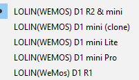
I have problems for upload idk what board need to use for work…
idk if my wemos is D1 or D2… I just similar to arduino UNO. (size)
The problem is when i upload with
Serial prints working but relay (outputs) dont work…
When i upload with
Relay Works but Serial Prints dont work…
idk what happend i dont find doc about this…
I just need 4 outputs and 2 inputs idk what board really need for buy.
Thx for all hlep!
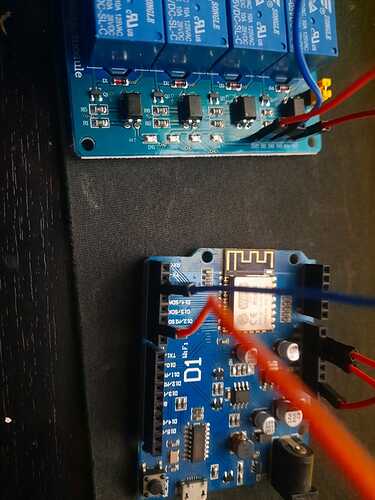
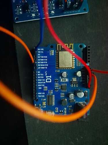
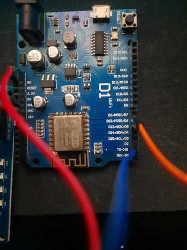
Some photos of your board would help.
It sounds like maybe you’re connecting the relays to the wrong pins.
Pete.
There is, sorry about double post but cant reply with photos only idk why.
That’s a D1 R1
Pete.
1 Like
Yes i use red pins, but idk what happend with 3 boards same issue, my code its ok ?
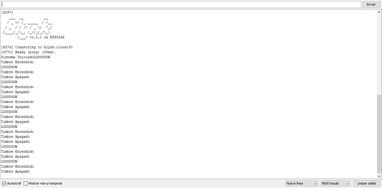
Code working correct when i put D6 to GND show me this in console.
EscuderoKevin:
show me this in console
That’s your serial monitor.
You’d be far better copying and pasting the contents of your serial monitor than posting a screenshot.
Pete.
TorNor
October 29, 2021, 11:37pm
10
Hi Kevin
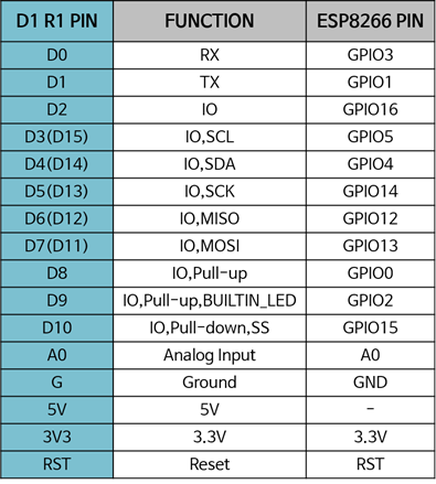
Try use for output D1, D2 , D7 and D0, D4, D5 for input
/Torben
John93
October 30, 2021, 4:15am
11
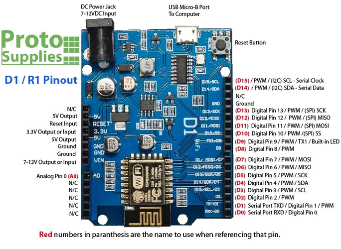
This is the WeMos D1 pin mapping
#define BLYNK_TEMPLATE_ID           ""
#define BLYNK_DEVICE_NAME           "Wemos Living"
#define BLYNK_AUTH_TOKEN            ""


#define BLYNK_PRINT Serial

#include <ESP8266WiFi.h>
#include <BlynkSimpleEsp8266.h>


BlynkTimer timer;

char auth[] = BLYNK_AUTH_TOKEN;

char ssid[] = "Jarvis Modem";
char pass[] = "";


const int timbre = D7;
const int btntimbre = D5;

int estadotimbre = LOW;
int estadobtntimbre = LOW;

void setup()
{
  // Debug console
  Serial.begin(9600);
  Blynk.begin(auth, ssid, pass);


  pinMode(timbre, OUTPUT);
  pinMode(btntimbre, INPUT_PULLUP);


  Serial.print("Sistema Iniciado");
  timer.setInterval(100L, checkearbotontimbre);

}

void loop()
{
  Blynk.run();
  timer.run();

}

void checkearbotontimbre()
{

  if (digitalRead(btntimbre) == LOW) {
    if (estadobtntimbre != LOW) {
      Serial.print("LOOOOOOW");
      Serial.println();
      SonarTimbre();
      Blynk.notify("[CASA] Alguien toco el timbre.");
    }
    estadobtntimbre = LOW;
  } else {
    estadobtntimbre = HIGH;
  }
}


void SonarTimbre()
{
  digitalWrite(timbre, LOW);
  Serial.print("Timbre Encendido");
  Serial.println();
  timer.setTimeout(2000L, ApagarTimbre);  // Run ActionOFF function in 5 seconds
}

void ApagarTimbre()
{
  Serial.print("Timbre Apagado");
  Serial.println();
  digitalWrite(timbre, LOW);
  estadobtntimbre = !estadobtntimbre;
}
Not working… i test with 4 wemos idk what happend.Change Wires, change Relays , change USB cable i think the problem is the selected board in arduino or the code its not ok.
EscuderoKevin:
idk what happend
We don’t know either, because you’re not providing information to us about how your hardware is actually connected to your board (in the form of a schematic), how your relays are powered and whether they are active LOW or active HIGH relays.
You also havent elaborated on what this statement means…
EscuderoKevin:
The problem is when i upload with
Serial prints working but relay (outputs) dont work…
When i upload with
Relay Works but Serial Prints dont work…
Pete.
mmm sorry about my english, im from argentina.
Wemos powered with PIN 12V 2A. 4 Relays Modules Poweres with Wemos (Working if i put simple code with virtual pins. Example if i put datastream V1 and BLYNK_WRITE(V1) with digitalWrite to Relays Working Perfect)
But when i use my code for read Physycall button dont work.
4 MODULE RELAY ------- WEMOS
GND ------- GND
Button with with GND for check physicall button its conected to D4. When i give GND to D4 Serial Prints (Funcionts Working Perfect but relay dont work)
John93
October 31, 2021, 10:08am
15
@EscuderoKevin You would like to control the relay using the app and a button, am I right ?
Your code is checking pin D5
Pete.
Yep, Control 2 Relays.
When physical button pushed ON RELAY 1 , 5 SECONDS LATER STOP RELAY 1.
When 2cond physical button pushed ON RELAY 2. When pushed agian OFF RELAY 2. (This code is simple)
    // When App button is pushed - switch the state
BLYNK_WRITE(V2) {
  ledState = param.asInt();
  digitalWrite(ledPin, ledState);
}

void checkPhysicalButton()
{
  if (digitalRead(btnPin) == LOW) {
    // btnState is used to avoid sequential toggles
    if (btnState != LOW) {

      // Toggle LED state
      ledState = !ledState;
         ledState = !ledState;
      digitalWrite(ledPin, ledState);

      // Update Button Widget
      Blynk.virtualWrite(V2, ledState);
    }
    btnState = LOW;
  } else {
    btnState = HIGH;
  }
}
Relay 1 its only controlled with physical button.
Yes i see that but i conected correct.
Please post a schematic, which matches your actual hardware wiring setup.
Pete.
John93
October 31, 2021, 10:20am
20
First, you can try this example : Blynk Example Browser
Second, blynk.notify has been replaced with blynk.logevent, check this outhttps://docs.blynk.io/en/getting-started/events-tutorial
![]()
![]()
