Hi everyone!
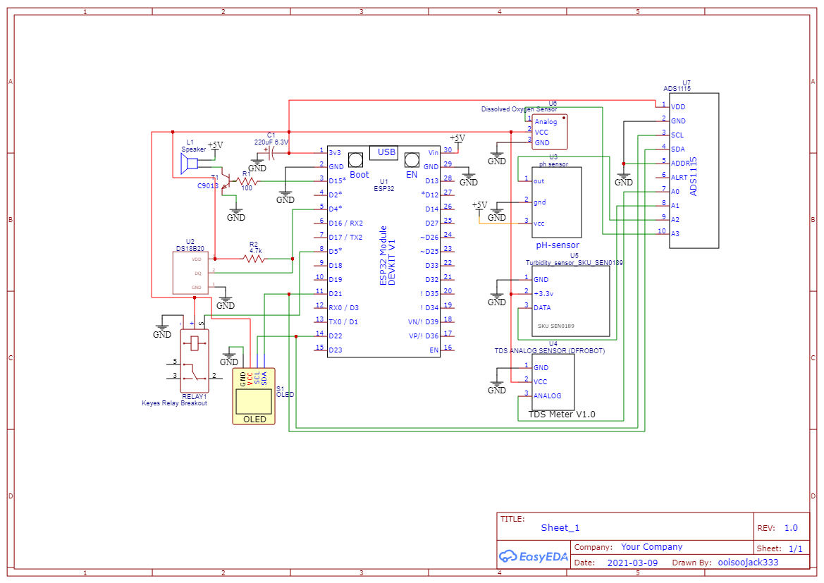
Not sure if anyone has posted similar stuff here before, but I made a water quality monitoring device for fish farming. The device uses an ESP32 DevKit V1 as the “brain”. Currently, it only has these sensors installed:
- DS18B20 Temperature Sensor
- SEN0161 pH Sensor V1.1
- SEN0189 Turbidity Sensor
- SEN0244 TDS Sensor
It also has:
- A relay to control an aquarium air pump (the air pump should be turned on based on the SEN0237 Dissolved Oxygen Sensor readings, but I do not have one now, it is very expensive, so I have to trigger it using temperature values for now).
- A speaker to alarm the user when the device detects poor water quality (only pH and temperature sensor trigger it for now).
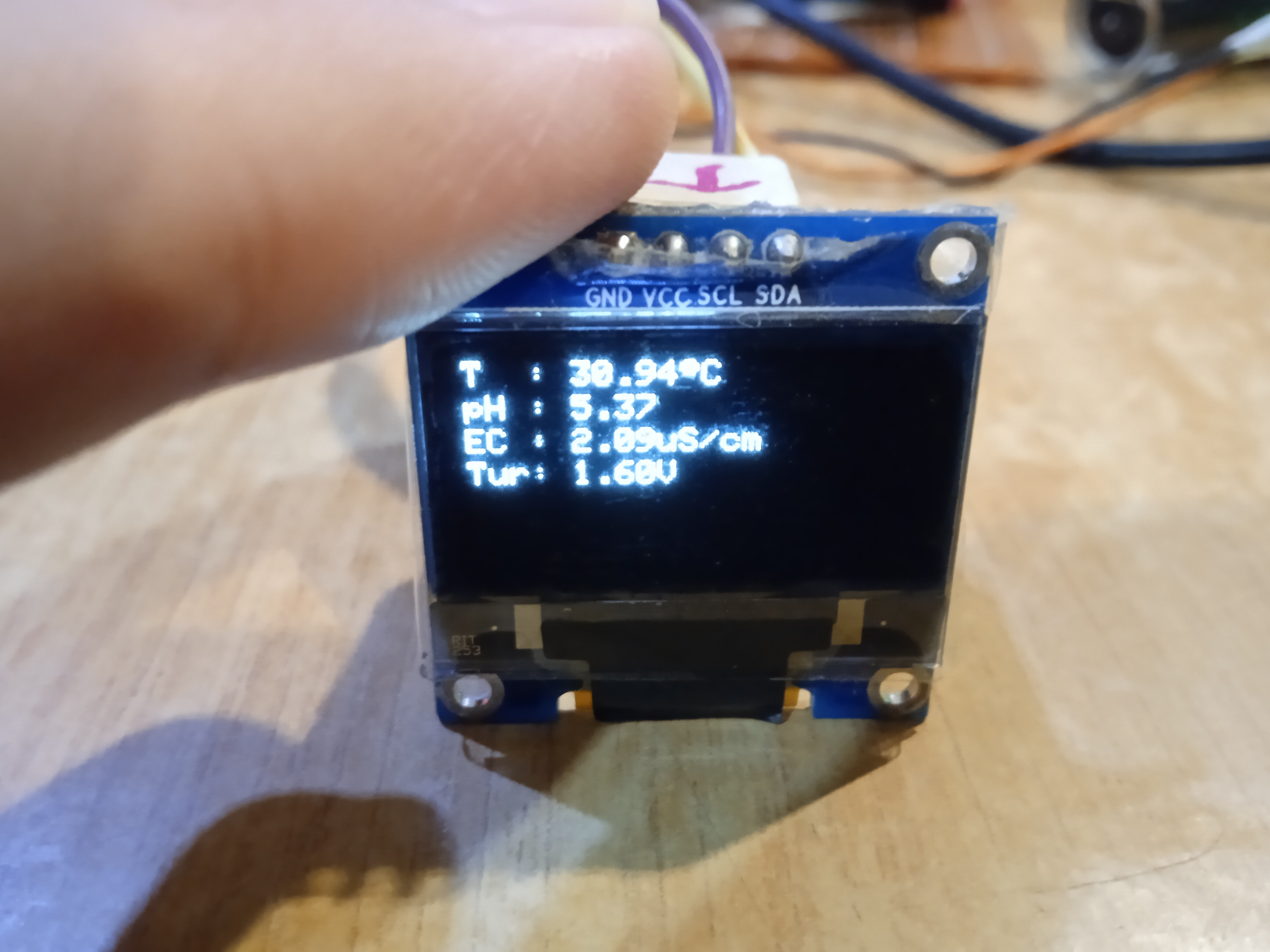
- An OLED Display in case if you do not have access to your phone.
- An ADS1115 16-Bit ADC to obtain more accurate readings from the sensors (because apparently, ESP32 ADC behaviour is umm… non-linear…)
I also used Thinger.io platform to plot a real-time graph to make datalogging easier (the Blynk SuperChart widget is great, but when it comes to datalogging, I find that Thinger.io is easier to work with… sorry…)
For power, I have only tried powering it via laptop USB, not sure what will happen when it is powered using a power bank for long periods of time (and of course, I have not done any current consumption measurement of the device, I will do it later, maybe…).
In future, I am planning to power it using solar panels and also add an Ammonia Sensor, Nitrite Sensor and Nitrate Sensor, if I can find the ones with enough documentation and not too expensive welp.
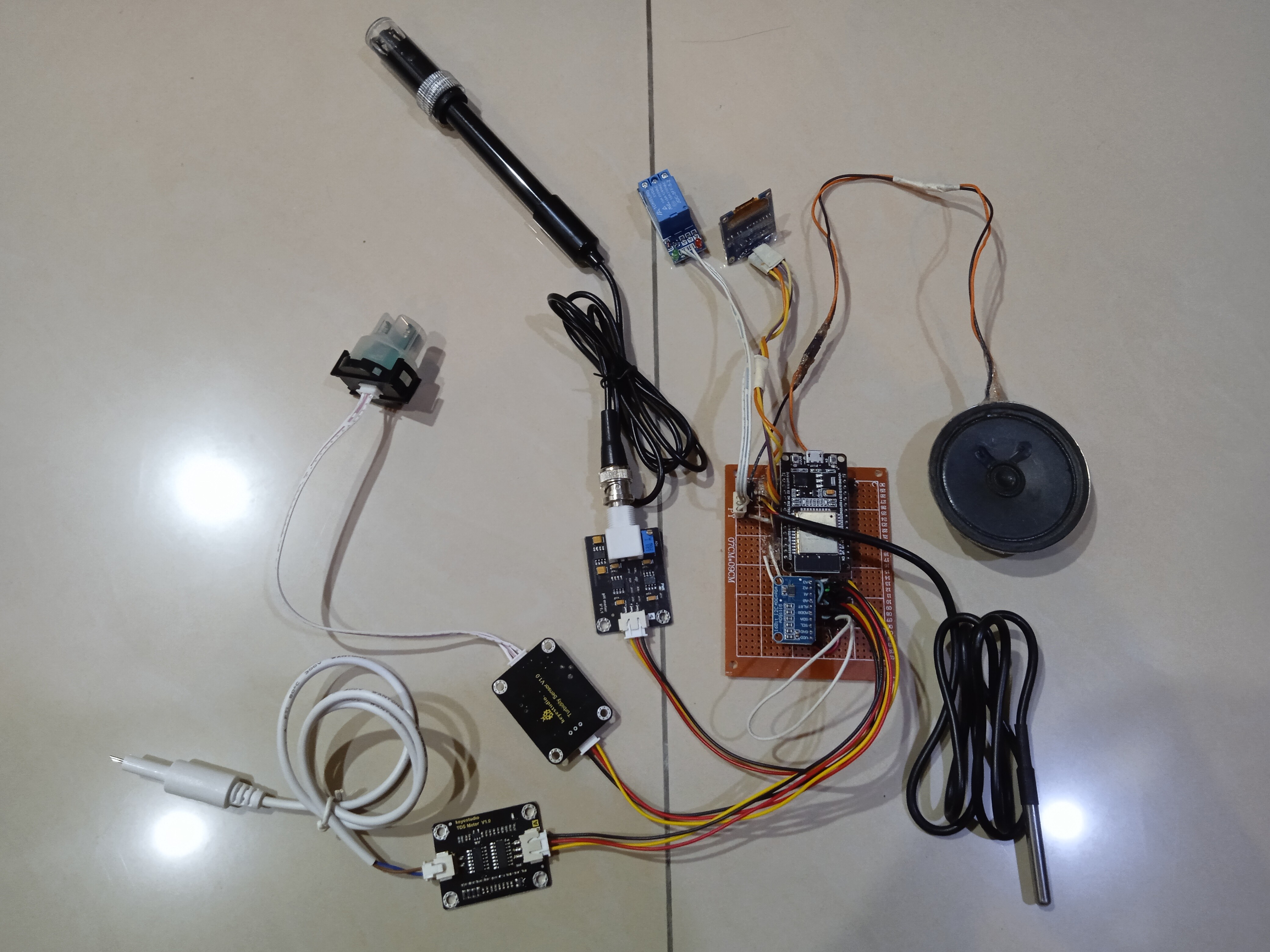
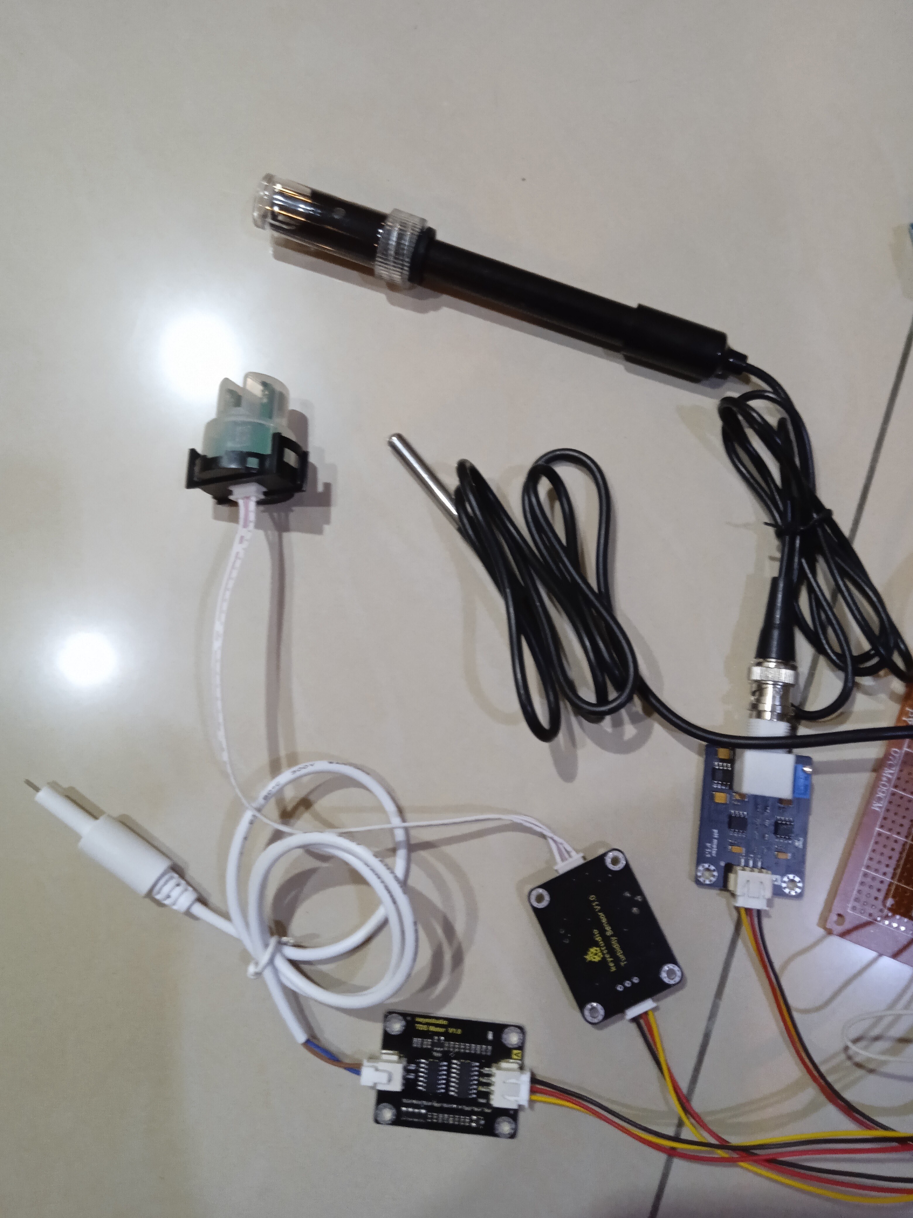
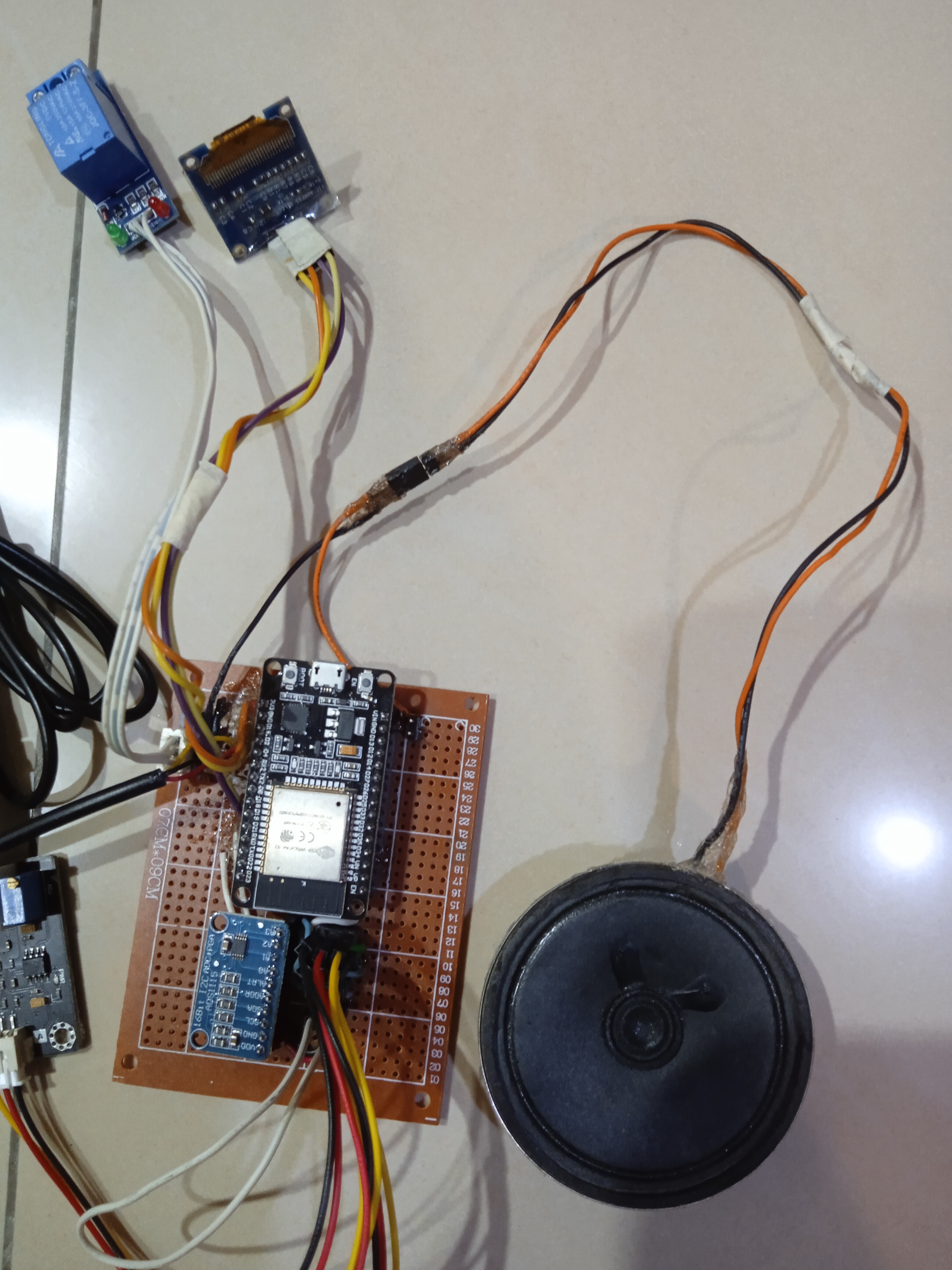
Here are some pictures of the prototype, it does not have an enclosure yet because I am too lazy for that haha.
The OLED Display:
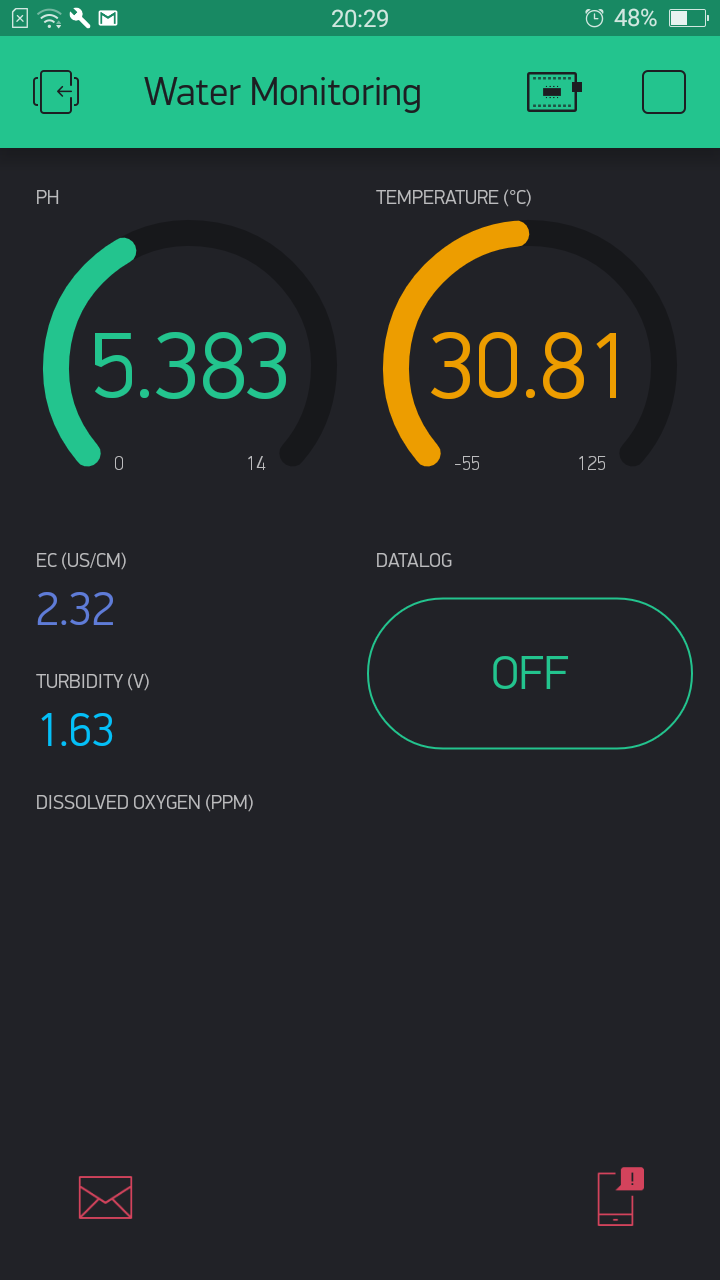
The Blynk App User Interface (Quite messy for now, I suck at designing UI welp):
Notification when sensor reading is outside the safe limit (?) (It can also send emails to the user) :
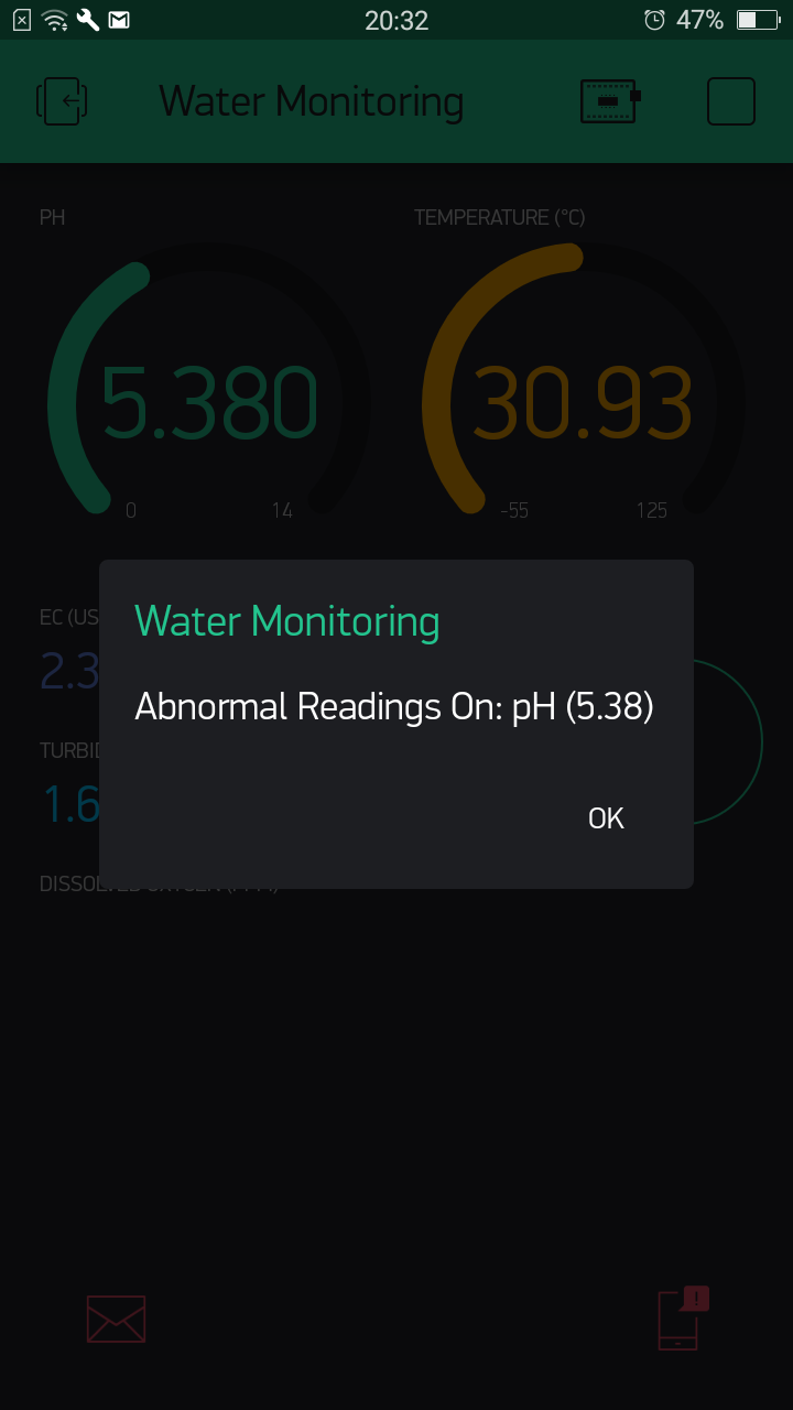
^ Every time the device detects poor water quality, it will send an email to the user once and a notification every 2 minutes until the water quality is back to normal.
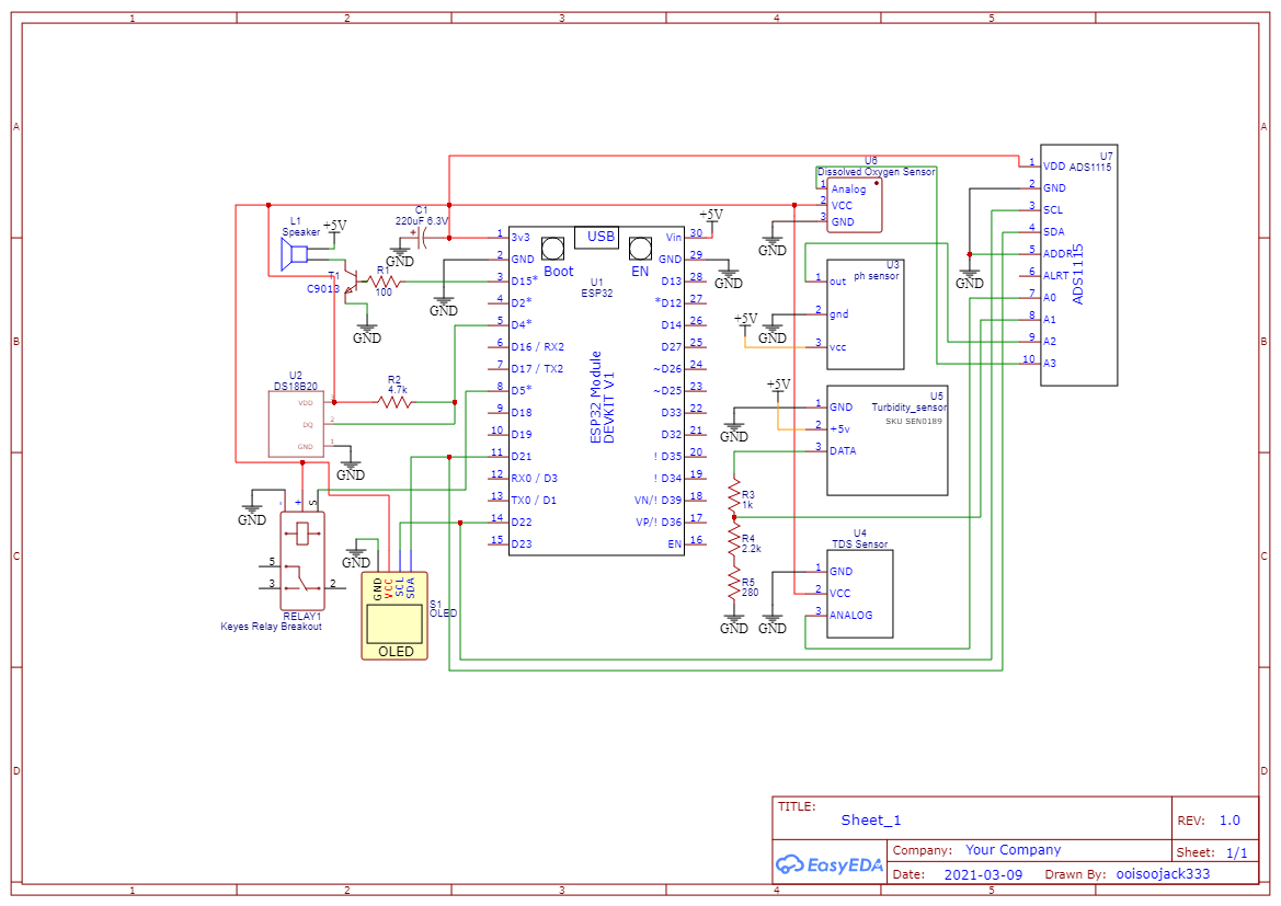
Here is the schematic:
And here is the code (it is also quite messy, not much comments in the code welp, and apologies to those who aged 10 years after looking at my code…):
#define BLYNK_PRINT Serial // For Blynk. Uncomment it to view connection log, comment it to disable print and save space
#define _DEBUG_            // For Thinger.io. Uncomment it to view connection log, comment it to disable print and save space
#define _DISABLE_TLS_      // For Thinger.io. For some reasons, this allows the connection to Thinger.io to work

//Libraries
//#include <Arduino.h>
#include <WiFi.h>
#include <WiFiClient.h>
#include <BlynkSimpleEsp32.h>
#include <DallasTemperature.h>
//#include <DFRobot_ESP_PH_WITH_ADC.h>
//#include <DFRobot_ESP_EC.h>
#include <ThingerESP32.h>
#include <Wire.h>
#include <Adafruit_ADS1X15.h>
#include <Adafruit_GFX.h>
#include <Adafruit_SSD1306.h>
//#include <Fonts/FreeMono9pt7b.h>

//Definitions
//#define tdsEcSen 36                     // TDS EC sensor
#define tempWire 4                        // Temperature sensor
//#define turbiSen 39                     // Turbidity sensor
//#define pHSen 34                        // pH sensor
#define relay 5                           // Relay pin
#define vRef 3.3                          // ESP32 reference voltage
#define adcRes 4096.0                     // ESP32 ADC resolution
#define USERNAME "nope"                // Thinger.io username
#define DEVICE_ID "nope"                 // Thinger.io Device ID
#define DEVICE_CREDENTIAL "nope"  // Thinger.io Device Credential
#define OLED_RESET -1
#define SCREEN_WIDTH 128 // OLED display width, in pixels
#define SCREEN_HEIGHT 64 // OLED display height, in pixels

Adafruit_ADS1115 ads;
Adafruit_SSD1306 display(SCREEN_WIDTH, SCREEN_HEIGHT, &Wire, OLED_RESET);
//DFRobot_ESP_PH_WITH_ADC ph;
OneWire oneWire(tempWire);
DallasTemperature tempSen(&oneWire);
BlynkTimer timer;
ThingerESP32 thing(USERNAME, DEVICE_ID, DEVICE_CREDENTIAL);

char auth[] = "nope"; // auth token
char ssid[] = "nope";                  // WiFi SSID.
char pass[] = "nope";                       // WiFi password. Set password to "" for open networks.
float voltsEC, voltsTurbi, voltspH, voltsDO;
float temperature = 25;
float ec = 0, tds = 0, ecCalibration = 1.1500, pH = 0;
int freq = 2000, channel = 0, resolution = 8;
int tempTrig = 0, tempEmail = 0, alarmPlay = 0;
int pHTrig = 0, pHEmail = 0;
int dataLog = 0;
int16_t adc0, adc1, adc2, adc3;

float round_to_dp( float in_value, int decimal_place ) {
  float multiplier = powf( 10.0f, decimal_place );
  in_value = roundf( in_value * multiplier ) / multiplier;
  return in_value;
}

BLYNK_WRITE(V5) {
  dataLog = param.asInt();
}

void readADC() {
  //int16_t adc0, adc1, adc2, adc3;

  adc0 = ads.readADC_SingleEnded(0);
  adc1 = ads.readADC_SingleEnded(1);
  adc2 = ads.readADC_SingleEnded(2);
  adc3 = ads.readADC_SingleEnded(3);

  voltsEC = adc0 * 0.000125;
  voltsTurbi = adc1 * 0.000125;
  voltspH = adc2 * 0.125;
  voltsDO = adc3 * 0.000125;
}

void getTemp() {
  tempSen.requestTemperatures();
  temperature = tempSen.getTempCByIndex(0);
  if (temperature > 40) {
    tempTrig = 1;
    if (tempEmail == 0) {
      tempEmail = 1;
      Blynk.email("Temperature Alert", String("Recorded Temperature: ") + temperature + String("°C"));
    }
    digitalWrite(relay, LOW);
  }
  else {
    tempTrig = 0;
    tempEmail = 0;
    digitalWrite(relay, HIGH);
  }
  Blynk.virtualWrite(V0, temperature);
}

void getTdsEc() {                // read the analog value more stable by the median filtering algorithm, and convert to voltage value
  float tempCoefficient = 1.0 + 0.02 * (temperature - 25.0);          // temperature compensation formula: fFinalResult(25^C) = fFinalResult(current)/(1.0+0.02*(fTP-25.0));
  float voltageComp = (voltsEC / tempCoefficient) * ecCalibration;                     // temperature and calibration compensation
  tds = (133.42 * pow(voltageComp, 3) - 255.86 * pow(voltageComp, 2) + 857.39 * voltageComp) * 0.5; // convert voltage value to tds value
  ec = 2 * tds;
  Serial.println(voltsEC);
  // Sensor Values to Blynk application
  Blynk.virtualWrite(V1, ec);
}


// equation: https://forum.arduino.cc/t/getting-ntu-from-turbidity-sensor-on-3-3v/658067/14
void getTurbidity() {
  /*if (volt < 1.6) {
    ntu = 3000;
    }
    else if (volt < 2.77) {
    ntu = -2572.2 * pow(volt, 2) + 8700.5 * volt - 4352.9;
    }
    else{
    ntu = 0;
    }

    Blynk.virtualWrite(V2, ntu);*/
  Blynk.virtualWrite(V2, voltsTurbi);
}


//got problem here
void getpH() {
  //Serial.println(adc2);
  //voltspH = reverseReading * 0.125;
  //pH = ph.readPH(voltspH, temperature); // convert voltage to pH with temperature compensation
  pH = 0.000528 * (float)adc2 - 0.25; //c = 0.4628
  Blynk.virtualWrite(V3, pH);
  //ph.calibration(voltspH, temperature); // calibration process by Serail CMD
  if (pH >= 20 || pH <= 6) {
    pHTrig = 1;
    if (pHEmail == 0) {
      pHEmail = 1;
      Blynk.email("pH Alert", String("Recorded pH: ") + pH);
    }
  }
  else {
    pHTrig = 0;
    pHEmail = 0;
  }
}

//not yet
void getDO() {

}

void displayUpdate() {
  display.setTextSize(1);
  display.setTextColor(WHITE);
  display.setCursor(0, 0);
  display.clearDisplay();
  display.println("T  : " + String(temperature) + (char)247 + "C");
  display.setCursor(0, 10);
  display.println("pH : " + String(pH));
  display.setCursor(0, 20);
  display.println("EC : " + String(ec) + "uS/cm");
  display.setCursor(0, 30);
  display.println("Tur: " + String(voltsTurbi) + "V");

  //display.println("DO  : " + String(temperature) + (char)247 + "C");
  display.display();
}

void allNotif() {
  String notifMessage = "";
  if (tempTrig == 1 || pHTrig == 1) {
    if (tempTrig == 1) {
      notifMessage += " Temperature (" + String(temperature) + "°C) ";
    }
    if (pHTrig == 1) {
      notifMessage += " pH (" + String(pH) + ") ";
    }
    Serial.println(notifMessage);
    Blynk.notify(String("Abnormal Readings On:") + notifMessage);
  }
  else {

  }
}

void alarmSound() {
  if (tempTrig == 1 || pHTrig == 1) {
    if (alarmPlay == 0) {
      alarmPlay = 1;
      ledcWriteTone(channel, 500);
      ledcWrite(channel, 5);
      delay(10);
    }
    else {
      alarmPlay = 0;
      ledcWriteTone(channel, 500);
      ledcWrite(channel, 0);
      delay(10);
    }
  }
  else {
    ledcWriteTone(channel, 500);
    ledcWrite(channel, 0);
    delay(10);
  }
}

void thingerSend() {
  thing["senVal"] >> [] (pson & out) {
    out["Temperature"] = temperature;
    out["pH"] = pH;
    out["EC"] = ec;
    out["TDS"] = tds;
    out["Turbidity"] = voltsTurbi;
  };

  if (dataLog == 1) {
    thing.write_bucket("sensorValues", "senVal");
  }
  else {

  }
}


void setup()
{
  //startTime = millis();
  Serial.begin(115200);                   // begin serial monitor, 9600 is recommended for ESP8266 shield setup
  Blynk.begin(auth, ssid, pass);  // start Blynk
  thing.add_wifi(ssid, pass);
  display.begin(SSD1306_SWITCHCAPVCC, 0x3C);
  pinMode(relay, OUTPUT);
  digitalWrite(relay, HIGH);
  ledcSetup(channel, freq, resolution);
  ledcAttachPin(15, channel);
  display.display();
  //display.setFont(&FreeMono9pt7b);
  ads.setGain(GAIN_ONE);
  ads.begin();
  for (int i = 0; i < 3; i++) {
    ledcWrite(channel, 10);
    ledcWriteTone(channel, 1046.50);
    delay(10);
    ledcWrite(channel, 0);
    delay(100);
  }
  display.clearDisplay();
  timer.setInterval(5000L, readADC);
  timer.setInterval(5100L, getTemp);
  timer.setInterval(5200L, getTdsEc);
  timer.setInterval(5300L, getTurbidity);
  timer.setInterval(5400L, getpH);
  timer.setInterval(5500L, getDO);
  timer.setInterval(5600L, displayUpdate);
  timer.setInterval(120000L, allNotif);
  timer.setInterval(2000L, alarmSound);
  timer.setInterval(60000L, thingerSend);
}

void loop()
{
  //currTime = millis();
  Blynk.run();
  timer.run();
  thing.handle();

}
Problems that I still cannot solve completely:
- Calibration
Calibration on the TDS sensor and the pH sensor is very challenging as their readings seems to take a very long time to settle at somewhere (or not at all). At first, I thought the circuit is noisy so I added a capacitor between 3.3V and GND but that makes no difference. I searched a few tutorials online to solve this but to no avail, all I know is that for the sensors I have now, I can only do the calibration by jotting down their ADC values in different buffer solutions and then plot a graph in Excel to obtain an equation.
This is fine, but it also shows that the sensors are non-linear since the readings are pretty close but not exact, and I do not feel like going any further, I have spent too much time on just a single problem. Maybe I will buy better sensors or just wait until more documentation is out there.
I also wonder if my ADS1115 is the culprit or not…
- Turbidity Sensor
You may have noticed that the unit for my Turbidity Sensor reading is in volts instead of some standards like NTU or FTU and so on.
That is because according to DFRobot’s wiki page (Turbidity_sensor_SKU__SEN0189-DFRobot), the sensor only works at 5V and has an analog output voltage of 0 - 4.5V, which will most likely kill the ESP32 or the ADS1115 at levels above 3.3V (the seller I purchased the sensor from is KeyesStudio (KS0414 Keyestudio Turbidity Sensor V1.0 - Keyestudio Wiki) but I think they are the same, just with a different brand name welp.). So I ended up connecting its VCC to 3.3V.
At this point, the sensor is incredibly inaccurate and only practical if it is trying to show the water turbidity qualitatively. Also, I read somewhere that some people doubt the voltage to NTU formula used is justifiable, and someone even said the sensor is only meant to provide rough readings of the water turbidity welp.
What are your thoughts? If you are an expert on these kinds of sensors or this type of project, I will be more than happy to hear some suggestions from you. Maybe I will post some updates when it is complete.
Stay safe and have a good one!
*also forgot to note that the safe limits for pH sensor and temperature sensor are not really safe, I set them that way so that the stupid speaker will not keep yelling at me, it is pretty hot here too welp.