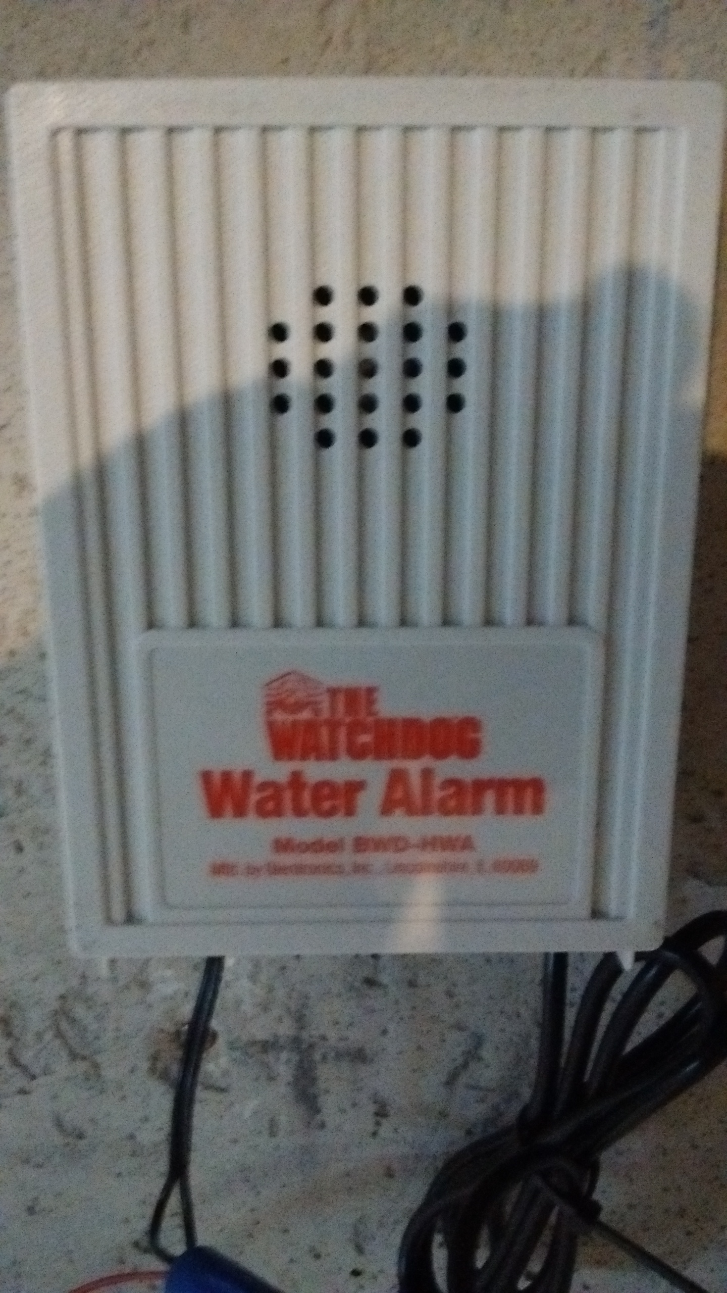
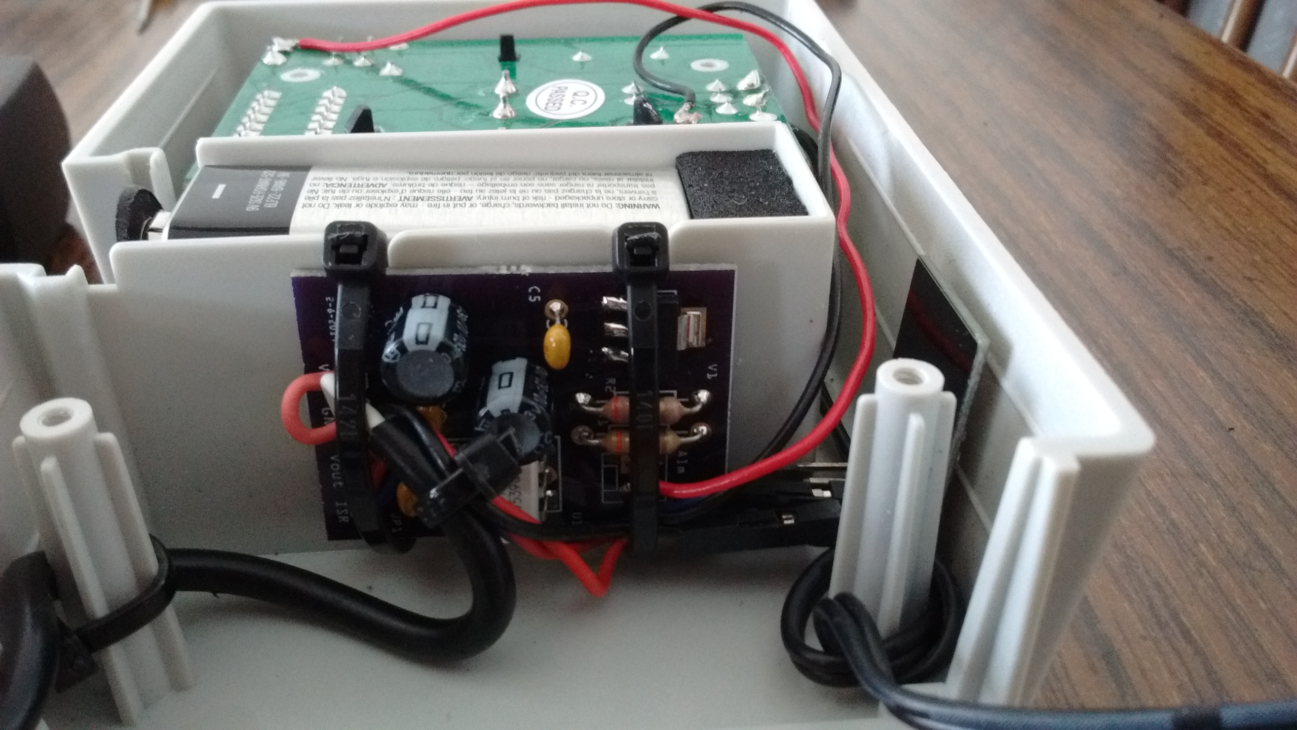
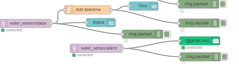
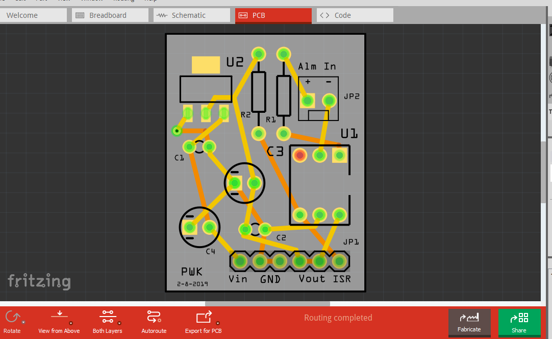
Modified basic water alarm by adding WiFi to allow for notification by email. The esp8266 connects via WiFi to a local Raspberry PI server running Node-RED and MQTT. The alarm has two sensors, one located near water heater and the other located in sump pump pit. If either one detects water an audible alarm will sound and MQTT message will be sent via MQTT payload, Node-RED, Blynk email node. I designed the circuit board which has a 3.3 regulator and opto isolator to separate 3.3V circuit from 9V battery circuit.

2 Likes
What is the sensor detecting actually? Your water supply is cut off sometimes that you need this to detect when it has water? If no water is detected then pump / heater are turned off?
For the power supply for Raspberry Pi (RPi) what kind of power supply you used? An RPi’s adaptor normal one 5VDC/2A?
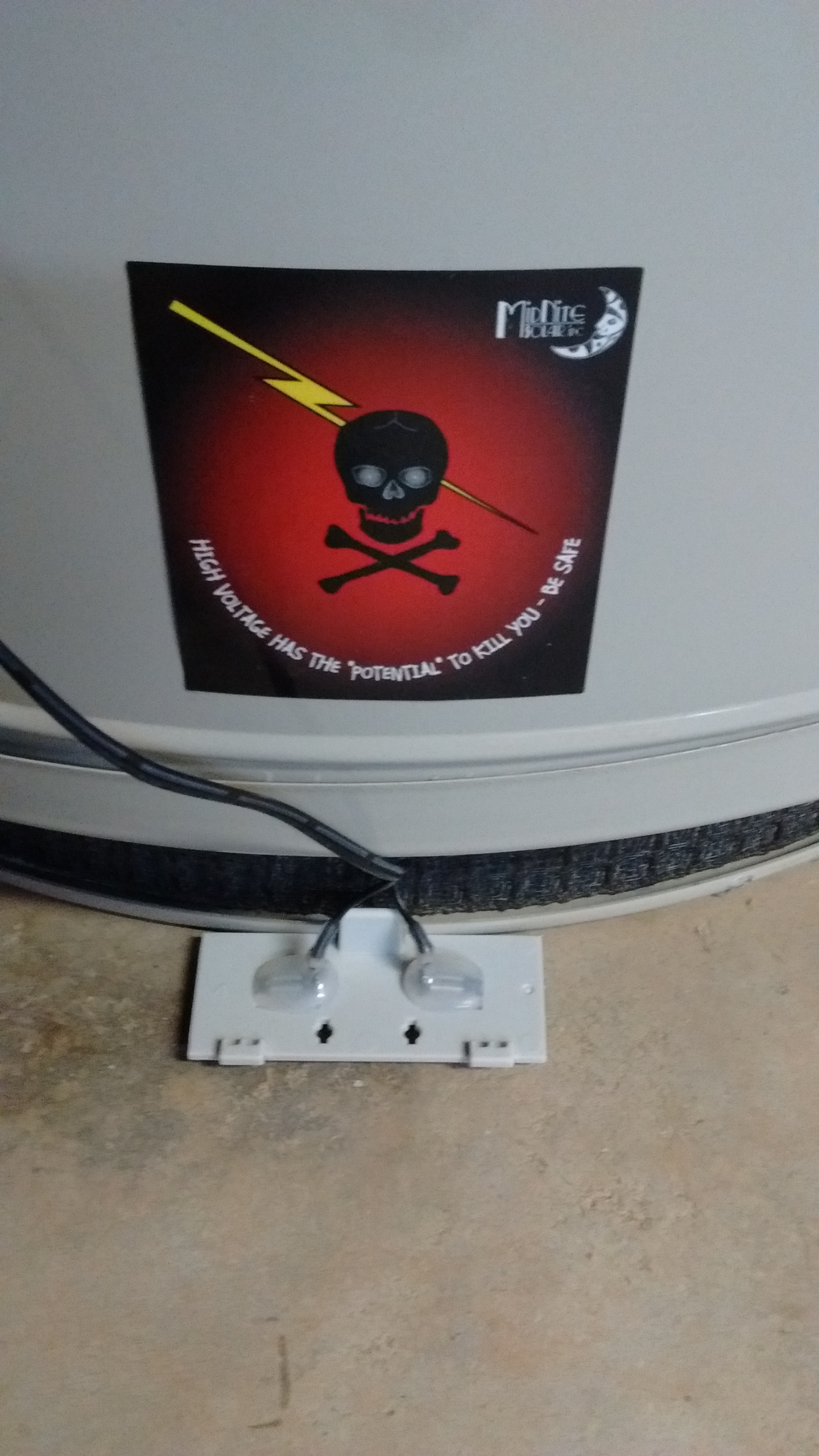
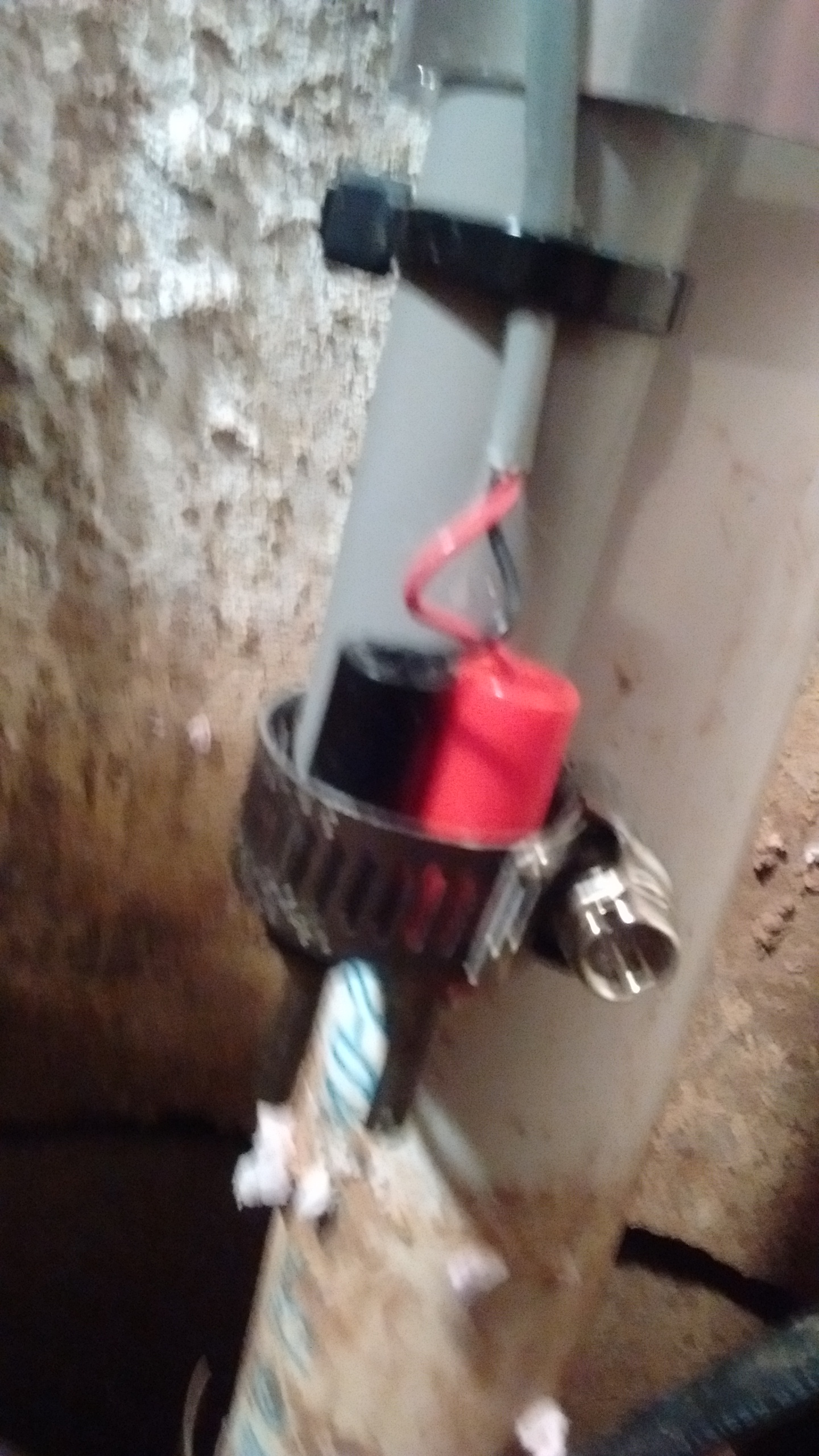
It’s a water leak detector. In its normal form the sensor contacts are on the bottom of the battery operated device and it stands on the floor. If there’s a leak then the water shorts out the contacts and the alarm sounds. This adds an ESP-01 to make it Wi-Fi enabled so you get alerts even if you’re out of earshot of the alarm and the sensors have been extended to move the main body of the device off the floor.
The power supply discussed here powers the ESP-01, not the Raspberry Pi.
Pete.
@PeteKnight: thanks for the info since I never use the heater at my end so no idea about it haha. Hence it means the RPi and ESP-01 came for the purpose together so I wonder why he does not use the common / simple power supply rather a separated 9VDC pack for only ESP that I am sure he needs some code for sleep mode? Ah yes he has chance to code additionally when the batt running out that he can come back to replace … as well as to see his partner once … sometimes haha
This device and the RPI server will be in different locations. What you’re seeing in the photos are the original circuit board for the water leak alarm, plus an ESP-01 and the power supply for the ESP-01.
The RPI Node-Red/MQTT server will be somewhere else within the house.
Pete.
2 Likes
Thank you PeteKnight you are correct on all topics. I did consider battery only operation and sleep mode for ESP-01 when designing the project. The capacity (mAh) of a 9 volt battery is approx. 500. The 3.3 volt regulator draws approx. 2 ma with no load and 9 volt input. This would yield only about 10 days of run time from battery. With the setup I have now the only time there is current draw from the battery is when the alarm sounds. Normal operation no current draw, the battery should last a very long time. Also the ESP-01 sends out status messages via MQTT that it is functioning correctly.
Paul
Hi Paul,
If I were you I’d add something to measure the battery voltage level, so you’d never run dry  to save on battery you’d need to use 2 GPIOs, but that’s not a problem.
Problem is that to measure battery voltage you need access to the analogue pin, and that’s not broken-out on the ESP-01.
If you have good eyesight and a steady hand you could solder a very fine wire on to the analogue pin on the chip.
The other issue is that the standard way to measure battery voltage is with a two resistor voltage divider. However, this creates a battery drain of its own, which defeats the object of the exercise to some extent. You can get around this by adding say a P-channel FET and using a a digital pin to turn the FET on when you wnat to take a voltage reading, but that’s adding to the component count.
But as @PWK says:
I don’t think that measuring the battery voltage is necessary anyway.
Pete.
Agree @PeteKnight but I saw this [quote=“PWK, post:6, topic:35091”]
Also the ESP-01 sends out status messages via MQTT that it is functioning correctly.
[/quote] and that’s why I suggested the measurement… and as I said before, you could just use 2 GPIOs, so the divider (the 2nd resistor) ends on the second GPIO that is held HIGH until you need to do the calculation. Also, if you use the divider in the MOhm range, the current draw will be minimal. But yeah, if it will only wake up in case of a water leak it’s not a problem.
Thanks @ericssson and @PeteKnight for the interest in the project and the information. Another reason for using ac power wall adaptor is peace of mind the system is going to function. The last several days my sump pump has been running approx every 15 minutes. If it were to fail and my basement were to flood, I would loose some very expensive woodworking equipment and projects .Just completing arts and craft chair 200+ hours! I need the system to be reliable. The next electronic project is to interface two 100 ah solar system batteries in the garage to the sump pump in case of a power failure. Thanks again
Paul
1 Like