Virtual pin to control momentary latch relay

Hey Blynkers,

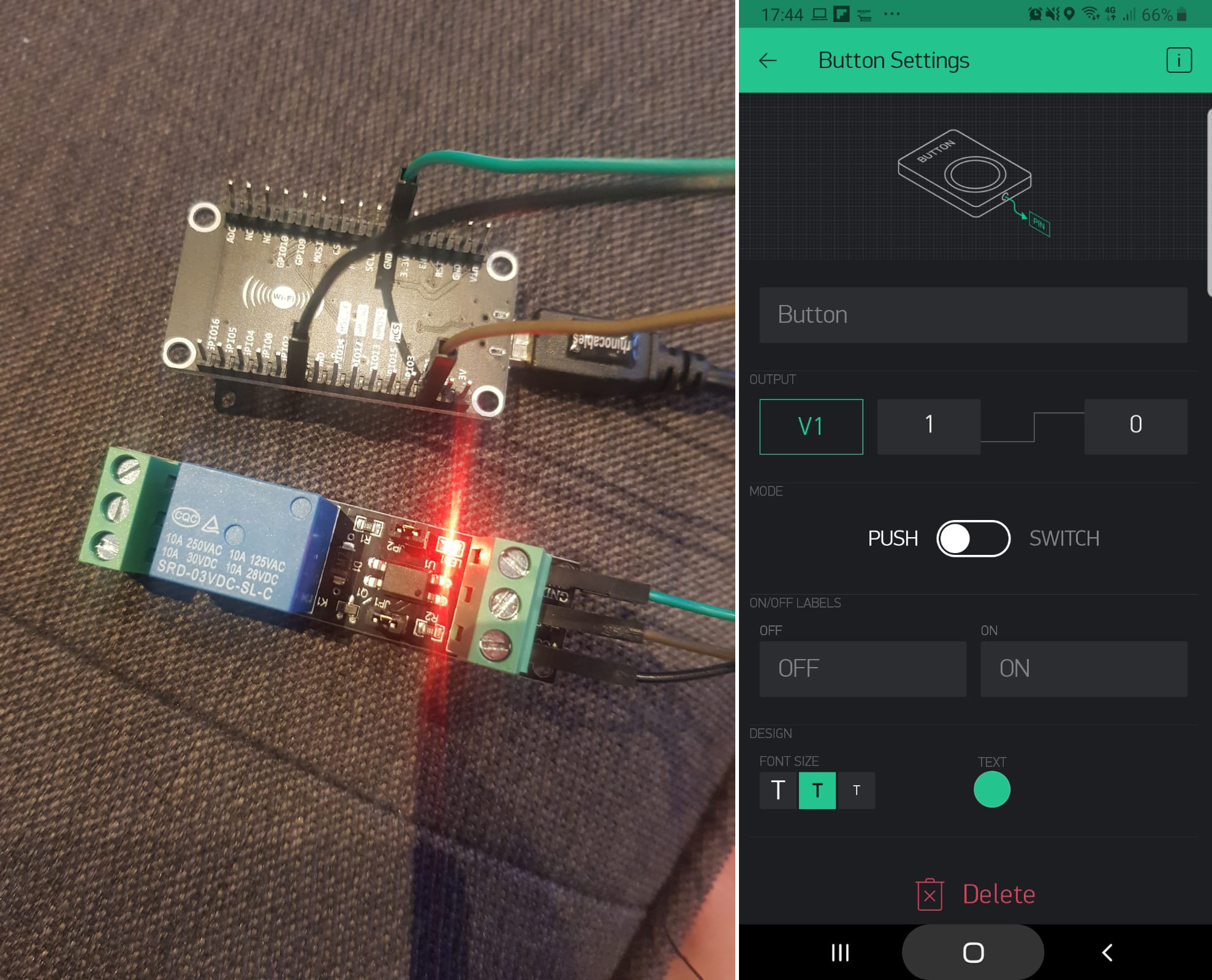
I’m a noob wanting to use a Wemos D1 mini + arduino IDE to open my garage door. The issue I’ve got is getting a relay to act like a momentary push switch. In the Blynk app, its fine. Just set the button to ‘push’. The problem is, I also want to be able to open/close the door using IFTTT webhooks. This works, however it latches the pin high = relay latches closed. I was hoping to use some code to get something like webhook pulls virtual pin high - code in Wemos detects pin is high - runs a loop pulling the digital pin high for a second then low again.

I’ve looked for an answer in these forums, but still haven’t been able to pull it off. I’m not a coder at all, the following was copy/pasted from other projects here, but doesn’t work. I’m sure this is a fairly simple task, can anyone help?

#define BLYNK_PRINT Serial    // Comment this out to disable prints and save space
#include <ESP8266WiFi.h>
#include <BlynkSimpleEsp8266.h>
#include <SimpleTimer.h>
SimpleTimer tripWire;

// You should get Auth Token in the Blynk App.
// Go to the Project Settings (nut icon).
char auth[] = "***";

// Your WiFi credentials.
// Set password to "" for open networks.
char ssid[] = "";
char pass[] = "";

int outputPin = D5;
int inputPin = V1;
int val = 0;

void setup()
{
  Serial.begin(9600);
  Blynk.begin(auth, ssid, pass);
  }
//pasted code starts here
BLYNK_WRITE(inputPin) {
  int pinValue = param.asInt();
  if (pinValue==HIGH) { // virtual pin V1 goes HIGH when pressed in the app, goes LOW when released.
    tripActivate();
  }
}

void tripActivate() {
  digitalWrite(outputPin, HIGH);
  tripWire.setTimeout(1000L, tripDeactivate);
}

void tripDeactivate() {
  digitalWrite(outputPin, LOW);
}
//pasted code ends here
void loop()
{
  Blynk.run();
}

Far simplier than you think. EDIT: just read over your questions again and made an edit below

BLYNK_WRITE(inputPin) {
  if (param.asInt()) { // act only on the HIGH and not the LOW of the momentary
    digitalWrite(outputPin, !digitalRead(outputPin));  // invert pin state just once
    tripWire.setTimeout(1000L, [](){
      digitalWrite(outputPin, !digitalRead(outputPin));  // then invert it back after 1000ms
    });
  }
}

This wins hands down for me:

rather than this gibberish, but I’m not known for concise code :slight_smile:

1 Like

Since edited my post too :wink: But you know the format looks different but tis the same code basically.

(IF STATEMENT) ? TRUE : FALSE;

2 Likes

Appreciate the input guys. I had a few issues, but managed to get it working. I’ll write down my experience for anyone else who may stumble across this in the future.

The code didn’t seem to work initially, although I figured it was a problem with the pinout declarations(?). After much testing I found that the following wasn’t working for whatever reason.

int outputPin = D1;
int inputPin = V1;
int val = 0;

I have no idea what I’m doing wrong here, but if I put the pin names (D1 and V1) directly into the rest of the code, things started working.

Adding the ‘==1’ got the relay to latch, but it wouldn’t shut off again.

 if (param.asInt()==1){  // act only on the HIGH and not the LOW of the momentary

I’m a bit worried to paste what I did next, as using a delay function seems to be like swearing in public around here. Nevertheless, removing the timer code and replacing it with delay finally got the relay to unlatch.

 delay(200);

Finally, I needed to pull V1 low again.

 Blynk.virtualWrite(V1, LOW);

And it worked! The code may be the equivalent of a donkey pulling a porsche, but it does what I need it to. I’m an extreme beginner at this stuff so hopefully this post will help somebody in my position one day.


void setup()
{
  Serial.begin(9600);
  Blynk.begin(auth, ssid, pass);
  pinMode (D1, OUTPUT);
  }
//pasted code starts here

BLYNK_WRITE(V1) {
   if (param.asInt()==1){  // act only on the HIGH and not the LOW of the momentary
    digitalWrite(D1, !digitalRead(D1));  // invert pin state just once
//    tripWire.setTimeout(1000L, [](){
    delay(200);
    digitalWrite(D1, !digitalRead(D1));  // then invert it back after 1000ms
    Blynk.virtualWrite(V1, LOW);
//    });
  
    }}
//pasted code ends here

void loop()
{
  Blynk.run();
}

Thanks again for your input Jamin and Costas.

I believe the correct way of doing this would be…

#define outputPin 1
#define inputPin V1

No delays, garsh darnit or we kick your donkey :stuck_out_tongue_winking_eye: outta here (but we keep the Porch :house:).

Actually very short delays CAN be used, as long as they are not cumulative or large enough in of themselves to cause a heartbeat timeout (generally even 1-2 seconds can start causing potential issues)… @Jamin’s solution, while so condensed into uber coder shorthand as to be indistinguishable from magic :stuck_out_tongue_winking_eye: … would have better suited your needs, and allowed for a non-blocking relay latch ranging well into multiples of minutes/hours if needed.

Goober level coder translation follows :wink:

BLYNK_WRITE(inputPin) {
  if (param.asInt()) { // act only on the HIGH and not the LOW of the momentary
    digitalWrite(outputPin, !digitalRead(outputPin));  // invert pin state just once
    tripWire.setTimeout(1000L, [](){
      digitalWrite(outputPin, !digitalRead(outputPin));  // then invert it back after 1000ms
    });
  }
}

That == this…

#define outputPin 1
#define inputPin V1

BLYNK_WRITE(inputPin) {
  if (param.asInt() == 1) { // Run only when ON/HIGH state of button
    digitalWrite(outputPin, HIGH); // activate relay
    tripWire.setTimeout(1000L, DeactivateRelay);  // In 1 second, run the deactivate function call
  }
}

void DeactivateRelay() {
  digitalWrite(outputPin, LOW); // Deactivate relay
}

And, yes, I know it is pronounced Porsche… silly little cars… Lamborghini all the way!

if (param.asInt() == 1) {

… is exactly the same as …

if (param.asInt()) {

Both statments are TRUE when the button is held down.

Try my code again. Its flawless… just make sure you have the widget set as “PUSH” and not “SWITCH”.
If you have set it to push then you have no reason to use virtualSync since when you release the button it goes back to 0/LOW.

BLYNK_WRITE(inputPin) {
  if (param.asInt()) { // act only on the HIGH and not the LOW of the momentary
    digitalWrite(outputPin, !digitalRead(outputPin));  // invert pin state just once
    tripWire.setTimeout(1000L, [](){
      digitalWrite(outputPin, !digitalRead(outputPin));  // then invert it back after 1000ms
    });
  }
}

Also @Gunner is correct as below since these vars will never change.

Be sure to always use the GPIO pin number and not the printed digitalpin reference (ie D1, D2 etc).
Also on the WeMos its best to avoid a few certain pins. I cant remember which ones but bascially D4, D5 and the pins you should use on your projects first. So if you use D4, the declare should be int outputPin = 2; ie GPIO02

1 Like

Looking back at your original post, and noticed you have not started the BlynkTimer.
Probably the cause of your issues and why my code snippet didnt work for you.

void loop()
{
  Blynk.run();
  tripWire.run(); // missing this very important line to make the timer work
}

And if the relay is open when the MCU boots then just set the pin to the correct state 1 line above your pinMode line in setup()

void setup()
{
  // .. insert code 
  digitalWrite(2, HIGH); // set HIGH or LOW sttarting position
  pinMode(2, OUTPUT);
  // 
}
1 Like

For future reference, you’ve defined an INTEGER type variable, which (as far as Arduino is concerned) is a whole number between -32,768 and +32,767
Obviously “D1” and “V1” are alpha-numeric combinations that don’t fit this criteria, so can’t be stored as integers.

Pete.

1 Like

Great spotting @PeteKnight!

Hi, sorry to bring this thread back to life, but this is exactly what i’m trying to recreate. Another Gavin, another garage door, another person with very little knowledge stumbling along and copying code to make things work.

As a basic setup i’ve had it working where i can switch the relay on and off, but would like to turn it on, and after a few seconds it turns off automatically.

So far testing with the above suggestions it looks like my relay starts on, flickers very briefly and stays on.

Any help would be greatly appreciated.
Gav

#define BLYNK_PRINT Serial
#include <ESP8266WiFi.h>
#include <BlynkSimpleEsp8266.h>
BlynkTimer timer;

SimpleTimer tripWire;

;char auth[] = "*****";
char ssid[] = "***";
char pass[] = "***";


#define outputPin 1
#define inputPin V1


void setup()
{
  Serial.begin(9600);
  Blynk.begin(auth, ssid, pass);
  digitalWrite(2, HIGH); // set HIGH or LOW sttarting position
  pinMode(2, OUTPUT);
  }
//pasted code starts here
BLYNK_WRITE(inputPin) {
  if (param.asInt()) { // act only on the HIGH and not the LOW of the momentary
    digitalWrite(outputPin, !digitalRead(outputPin));  // invert pin state just once
    tripWire.setTimeout(1000L, [](){
      digitalWrite(outputPin, !digitalRead(outputPin));  // then invert it back after 1000ms
    });
  }
}

void loop()
{
  Blynk.run();
  tripWire.run(); // missing this very important line to make the timer work
}

@Gavin_Randall, you are close but you have a few things wrong.

  1. You are not using a good pin for your relay. It look like you have it connected to GPIO 1. This pin is used for serial communication to the PC through the USB Cable. It cannot be used in this application. I would switch it to GPIO 5.
  2. Your pinMode declaration is for the wrong pin. That is, it should be the same as the one your relay is connected to.
  3. I would call the pinMode before the digitalWrite.
  4. Change your button setting to switch, not push, and switch the 0 and 1 around.

Give the below a try, and see if you have any better luck. If the relay behaves opposite of what you are expecting, you may have to switch some stuff around.

#define BLYNK_PRINT Serial
#include <ESP8266WiFi.h>
#include <BlynkSimpleEsp8266.h>
BlynkTimer timer;

BlynkTimer tripWire;

char auth[] = "*****";
char ssid[] = "***";
char pass[] = "***";


#define outputPin 5


void setup()
{
  Serial.begin(9600);

  pinMode(outputPin, OUTPUT);
  digitalWrite(outputPin, HIGH); // set HIGH or LOW starting position

  Blynk.begin(auth, ssid, pass);
  
  }
//pasted code starts here
BLYNK_WRITE(V1) {
  if (param.asInt()) { // act only on the HIGH and not the LOW of the momentary
    digitalWrite(outputPin, LOW);  // invert pin state just once
    tripWire.setTimeout(1000L, [](){
      digitalWrite(outputPin, HIGH));  // then invert it back after 1000ms
     Blynk.virtualWrite(V1, LOW); // Set virtual button back to Off
    });
  }
}

void loop()
{
  Blynk.run();
  tripWire.run(); // missing this very important line to make the timer work
}
1 Like

Post several secs too late and be duplicated. You can try @Toro_Blanco solution

Try this code, but you need to change either

  1. Button Widget in the picture from V1 [1] [0] to V1 [0] [1]
  2. or change line 30 of the code from
#define ACTIVE_LOW_RELAY    true

to

#define ACTIVE_LOW_RELAY    false

and use pin D1 (GPIO5) of NodeMCU

Code

#define BLYNK_PRINT Serial
#include <ESP8266WiFi.h>
#include <BlynkSimpleEsp8266.h>

//PIN_D0 can't be used for PWM/I2C
#define PIN_D0            16        // Pin D0 mapped to pin GPIO16/USER/WAKE of ESP8266. This pin is also used for Onboard-Blue LED. PIN_D0 = 0 => LED ON
#define PIN_D1            5         // Pin D1 mapped to pin GPIO5 of ESP8266
#define PIN_D2            4         // Pin D2 mapped to pin GPIO4 of ESP8266
#define PIN_D3            0         // Pin D3 mapped to pin GPIO0/FLASH of ESP8266
#define PIN_D4            2         // Pin D4 mapped to pin GPIO2/TXD1 of ESP8266
//#define PIN_LED           2         // Pin D4 mapped to pin GPIO2/TXD1 of ESP8266, NodeMCU and WeMoS, control on-board LED
#define PIN_D5            14        // Pin D5 mapped to pin GPIO14/HSCLK of ESP8266
#define PIN_D6            12        // Pin D6 mapped to pin GPIO12/HMISO of ESP8266
#define PIN_D7            13        // Pin D7 mapped to pin GPIO13/RXD2/HMOSI of ESP8266
#define PIN_D8            15        // Pin D8 mapped to pin GPIO15/TXD2/HCS of ESP8266

//Don't use pins GPIO6 to GPIO11 as already connected to flash, etc. Use them can crash the program
//GPIO9(D11/SD2) and GPIO11 can be used only if flash in DIO mode ( not the default QIO mode)
#define PIN_D11           9         // Pin D11/SD2 mapped to pin GPIO9/SDD2 of ESP8266
#define PIN_D12           10        // Pin D12/SD3 mapped to pin GPIO10/SDD3 of ESP8266
#define PIN_SD2           9         // Pin SD2 mapped to pin GPIO9/SDD2 of ESP8266
#define PIN_SD3           10        // Pin SD3 mapped to pin GPIO10/SDD3 of ESP8266

#define PIN_D9            3         // Pin D9 /RX mapped to pin GPIO3/RXD0 of ESP8266
#define PIN_D10           1         // Pin D10/TX mapped to pin GPIO1/TXD0 of ESP8266
#define PIN_RX            3         // Pin RX mapped to pin GPIO3/RXD0 of ESP8266
#define PIN_TX            1         // Pin RX mapped to pin GPIO1/TXD0 of ESP8266

// Change this according to your relay's active type
#define ACTIVE_LOW_RELAY    true

#if ACTIVE_LOW_RELAY
  #define RELAY_ON    LOW
  #define RELAY_OFF   HIGH
#else
  #define RELAY_ON    HIGH
  #define RELAY_OFF   LOW
#endif

#define USE_LOCAL_SERVER    false

#if USE_LOCAL_SERVER
char server[] = "account.duckdns.org";
#define BLYNK_HARDWARE_PORT     8080
#endif

char auth[] = "***";
char ssid[] = "***";
char pass[] = "***";

// Use pin D1 for relay
#define outputPin       PIN_D1
#define inputPin        V1

BlynkTimer timer;

void clickRelay(int relayPin, uint32_t timeout)
{
  static int pinRelay = relayPin;

  Serial.println("Relay ON");
  digitalWrite(pinRelay, RELAY_ON);

  timer.setTimeout(timeout, []()
  {
    digitalWrite(pinRelay, RELAY_OFF);
    Serial.println("Relay OFF");
  });
}

//pasted code starts here
BLYNK_WRITE(inputPin) 
{
  if (param.asInt()) 
  { 
    // act only on the HIGH and not the LOW of the momentary  
    clickRelay(outputPin, 1000);
  }
}

void setup()
{
  pinMode(outputPin, OUTPUT);
  digitalWrite(outputPin, RELAY_OFF); // set HIGH or LOW sttarting position
  
  // Change your Serial terminal baud rate to 115200
  Serial.begin(115200);

  #if USE_LOCAL_SERVER
  Blynk.begin(auth, ssid, pass, server, 8080);
  #else
  Blynk.begin(auth, ssid, pass);
  #endif
}

void loop()
{
  Blynk.run();
  timer.run(); // missing this very important line to make the timer work
}

2 Likes

Thanks so much to you guys for replying so quick! These examples have sorted it. Doing exactly what i wanted it too and is now ready to be installed.

Some great info on the GPIO Pins which i feel i may have read before, or should have known… but didn’t. That will definitely help with the next project and may explain why some past projects weren’t working too.

Thanks again to both of you!!!
Gav

Thank you Thank you Thank you! You’ve solved a riddle that’s been plaguing me for weeks. Stopping the relay triggering on reset, everyone here made it possible. Thank you all :slight_smile: