I have a project where using a wired Ethernet connection, and providing power via the Ethernet cable (Power Over Ethernet) will be the neatest solution.
I bought one of these “LILYGO® TTGO T-Internet-POE ESP32-WROOM LAN8720A Chip Ethernet Adapter” boards to experiment with…
Although I won’t be running Blynk code on the board (I’ll be using my normal MQTT approach, with Node-Red acting as the bridge to Blynk) I thought I’d experiment a little first and get Blynk running on it.
There’s not much information available about the board, so getting started woith it can be a bit of a challenge. Hopefully this guide will help anyone who wants to use it with Blynk.
Board Overview
Serial Communication and programming
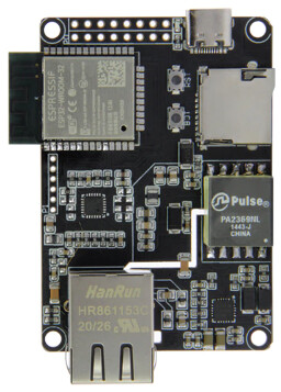
The board doesn’t have a built-in TTL to USB adapter (the USB-C adapter in the top right of this image is power only, and won’t be used anyway as I’ll be using POE), so you need an external TTL to USB (FTDI) adapter.
Lilygo make their own, which is designed to work with this board, so I picked-one up at the same time.
One of the reasons for doing this was that their own board (known as the “Downloader Expander board”) seemed to offer more GPIO pins (more on why this would be nice later)…
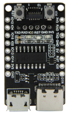
However, the pins that connect to the ESP32 board only have Rx, Tx, 3.3v, GND, GPIO0 and RST available, so these other pin headers around outside of the Downloader Expander board are redundant.
These is a miniature ribbon cable connector (at the top of the board in this image, between the two push buttons) but there isn’t a corresponding connector on the ESP32 board. That means that if you already have an FTDI adapter then you could use this instead.
A couple of things to look out for though…
- The downloader pins on the ESP32 board are 2mm pitch, not 0.1"
- The downloader board connects to the underneath of the ESP32 board, in an upside-down orientation
- The ESP32 board comes with a 2mm header to solder into the pins where the downloader board will fit. This header has to be soldered on to the back of the board, not the front, if you want to use the Lilygo downloader board
- The downloader pins aren’t labelled on the ESP32 board
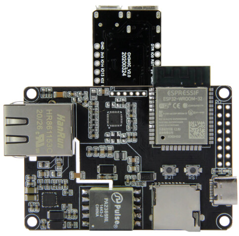
Here’s what the ESP32 board with the Lilygo Downloader Expander board fitted in the correct orientation looks like…
and these are the pinouts of the downloader expansion header on the ESP32 board - viewed from below…
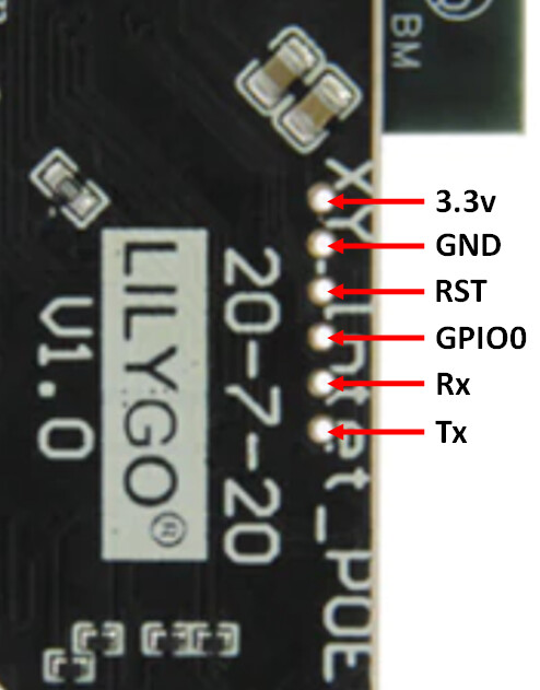
Don’t forget that if you use an FTDI adapter then you’ll need to cross the Rx and Tx lines over between the FTDI and the board.
The RST and GPIO0 connections aren’t needed when connecting an FTDI adapter.
Micro SD Card slot
The board has an onboard TF/Micro SD card slot, but there is one big issue with it - if there is a card in the slot then you can’t upload your sketch via the serial Downloader Expander board.
I don’t need the Micro SD card slot for my project, and I’ve not complicated this sketch by including any code that would initialise the card or demonstrate how to use it to read/write data. The example sketch on the Xinyuan-LilyGO GitHub site has the code in it…
https://github.com/Xinyuan-LilyGO/LilyGO-T-ETH-POE/blob/master/example/eth/eth.ino
These lines…
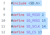
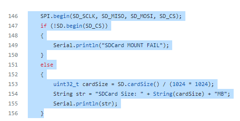
are the one that would need to be added back in to enable the card slot to work. There are plenty of examples on the interweb that show how to create files and read/write them using the SD.h library.
Power over Ethernet (POE)
The board can be powered via the USB-C connector or via POE. I find POE really useful, but also really confusing - mostly because of the different “standards” and the fact that there are so many variations within these standards that they don’t really guarantee that two devices will work together.
Apparently the board uses the 802.3af standard, but the important information is that it needs a 48v POE supply, with the Positive (+) supply on Ethernet pins 4 & 5 and the Negative (-) supply on Ethernet pins 7 & 8.
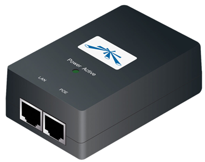
I’ve been using an Ubiquiti 48v 24W POE injector for my testing and it works fine.
GPIO Pins
Probably the biggest drawback with this board is that it has limited GPIOs available, and they are arranged in a 0.1" double pin header, and there are only 12 GPIOs available…
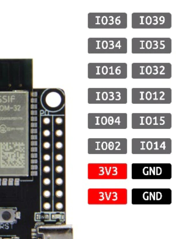
To make matters worse, one of these is pin 12 which will cause a boot failure if pulled HIGH at start-up, and four of the pins (34, 35, 36 & 39) are input only.
One solution would be to use one or more of these MCP23017 boards as port expanders…
but you’d need to be careful about power consumption over the POE interface if you’re powering peripherals from the 3.3v pins on the board.
Use of Ethernet and WiFi at the same time, or as a fallover interface
According to one website that I found…
it is possible to use both the Ethernet and WiFi interfaces together. This isn’t part of my requirement, and if I’m powering via POE there there is little point in falling over to the WiFi interface if the Ethernet one fails, as there’s unlikely to be any power getting to the board in that situation.
Hardware Variations
My board has a version number of V1.1 and a date of 22-1-20
It has the ESP32 WROOM chip and the LAN8720 Ethernet chip (located behind the RJ45 connector)
It seems that there might be versions with the ESP32 WROVER chip - which has PSRAM, and the TLK110 Ethernet chip. These require different settings in the sketch, and the example sketch from the Xinyuan-LilyGO has these various options in it, so I’ve retained them in my sketch. Check that you’re using the correct settings for your hardware.
Software
First of all, here’s the test environment I’m using:
- Arduino IDE 1.8.19
- ESP32 Core version 2.0.5
- Board type in the IDE - ESP32 Dev Module
- PSRAM - Disabled (My board has the ESP32 WROOM chip fitted, which has no PSRAM)
The sketch is quite confusing, because although it uses the ESP32 ETH.h library, this seems to piggy-back on the ESP32 WiFi library, so you’ll see commands like WiFi.onEvent even though we’re not using the WiFi library or the WiFi interface on the board.
There are various options available to comment/un-comment to cope with different hardware variations as discussed above.
There are also options regarding whether you use a dynamically assigned IP address (via DHCP) or a static IP address for the device, and whether you connect to Blynk via SSL or not.
Blynk.Air OTA
I’ve included the ability to do OTA updates via Blynk.Air and this works very well (much faster than over WiFi in my experience). As usual, you’ll need to increment the BLYNK_FIRMWARE_VERSION value if you want to use the Blynk.Air shipment default settings.
Other Blynk specific stuff
These lines of code:
#define BLYNK_TEMPLATE_ID "REDACTED"
#define BLYNK_DEVICE_NAME "REDACTED"
#define BLYNK_AUTH_TOKEN "REDACTED"
need to remain at the top of your sketch and need to be copied/pasted directly from the Device Info tab of the web console.
// Template ID, Device Name and Auth Token are provided by the Blynk.Cloud
// See the Device Info tab
#define BLYNK_TEMPLATE_ID "REDACTED"
#define BLYNK_DEVICE_NAME "REDACTED"
#define BLYNK_AUTH_TOKEN "REDACTED"

#define BLYNK_FIRMWARE_VERSION        "1.0.0" // For Blynk.Air OTA, Increment with each update

#define BLYNK_PRINT Serial

#include <ETH.h>

// You can use either the SSL or non-SSL library. Stick with SSL unless you have a good reason to change...
//#include <BlynkSimpleEsp32.h>
#include <BlynkSimpleEsp32_SSL.h>

#include <Update.h>   // For Blynk.Air OTA
#include <HTTPClient.h> // For Blynk.Air OTA

// Change this to match what it says on your ESP32 chip...
// #define ETH_CLK_MODE    ETH_CLOCK_GPIO0_OUT          // For ESP32 module with PSRAM (WROVER)
#define ETH_CLK_MODE ETH_CLOCK_GPIO17_OUT             // For ESP32 module without PSRAM (WROOM)

// Ethernet stuff - don't change unless you know more about this than me...
#define ETH_POWER_PIN -1          // Pin# of the enable signal for the external crystal oscillator (-1 to disable for internal APLL source)
#define ETH_TYPE ETH_PHY_LAN8720  // Type of the Ethernet PHY (LAN8720 or TLK110)
#define ETH_ADDR 0                // I²C-address of Ethernet PHY (0 or 1 for LAN8720, 31 for TLK110)
#define ETH_MDC_PIN 23            // Pin# of the I²C clock signal for the Ethernet PHY
#define ETH_MDIO_PIN 18           // Pin# of the I²C IO signal for the Ethernet PHY
#define NRST 5

static bool eth_connected = false;

BlynkTimer timer;

void WiFiEvent(WiFiEvent_t event) // Callback that is triggered when an Ethernet event occurs
{
  switch (event)
  {
  case ARDUINO_EVENT_ETH_START:
      Serial.println("ETH Started");
      // set eth hostname here
      ETH.setHostname("esp32-ethernet");
      break;
  case ARDUINO_EVENT_ETH_CONNECTED:
      Serial.println("ETH Connected");
      break;
  case ARDUINO_EVENT_ETH_GOT_IP:
      Serial.print("ETH MAC: ");
      Serial.print(ETH.macAddress());
      Serial.print(", IPv4: ");
      Serial.print(ETH.localIP());
      if (ETH.fullDuplex())
      {
        Serial.print(", FULL_DUPLEX");
      }
      Serial.print(", ");
      Serial.print(ETH.linkSpeed());
      Serial.println("Mbps");
      eth_connected = true;
      break;
  case ARDUINO_EVENT_ETH_DISCONNECTED:
      Serial.println("ETH Disconnected");
      eth_connected = false;
      break;
  case ARDUINO_EVENT_ETH_STOP:
      Serial.println("ETH Stopped");
      eth_connected = false;
      break;
  default:
      break;
  }
}


void setup()
{
    Serial.begin(115200);

    WiFi.onEvent(WiFiEvent); // Defines the callback (above) to be called when an Ethernet event occurs

    // Initialise the Ethernet interface...
    pinMode(NRST, OUTPUT);
    digitalWrite(NRST, 0);
    delay(200);
    digitalWrite(NRST, 1);
    delay(200);
    digitalWrite(NRST, 0);
    delay(200);
    digitalWrite(NRST, 1);
    ETH.begin(ETH_ADDR, ETH_POWER_PIN, ETH_MDC_PIN, ETH_MDIO_PIN, ETH_TYPE, ETH_CLK_MODE);

    // If you wnat to define a static IP address for your Ethernet device you can do it here using ETH.config()
    // The parameters are: (Device static IP address, Gateway, Subnet mask, DNS server IP)
    // Comment-out the ETH.config command if you want these to be parameters to be assigned by DHCP
    //ETH.config(IPAddress(192, 168, 1, 90), IPAddress(192, 168, 1, 1), IPAddress(255, 255, 255, 0), IPAddress(192, 168, 1, 1));

    Blynk.config(BLYNK_AUTH_TOKEN);
    Blynk.connect();

    timer.setInterval(1000L, myTimerEvent);
}

void loop()
{
  if (eth_connected)
  {
      Blynk.run();
  }
  timer.run();
}


void myTimerEvent()
{
  Blynk.virtualWrite(V1, millis() / 1000);
}


BLYNK_WRITE(InternalPinOTA) // For Blynk.Air OTA
{
  String overTheAirURL = param.asString();
  HTTPClient http;
  http.begin(overTheAirURL);
  int httpCode = http.GET();
  if (httpCode != HTTP_CODE_OK) {return;}
  int contentLength = http.getSize();
  if (contentLength <= 0) {return; }
  bool canBegin = Update.begin(contentLength);
  if (!canBegin) { return;}
  Client& client = http.getStream();
  int written = Update.writeStream(client);
  if (written != contentLength) {return;}
  if (!Update.end()) {return;}
  if (!Update.isFinished()) {return;}
reboot();
}


void reboot() // For Blynk.Air OTA
{
  ESP.restart();
  for (;;) {} // Wait here until the restart has begun
}
Results & Conclusions
The board works very well. It establishes an Ethernet connection quickly after start-up and Blynk connects quickly too.
If you’re powering via USB-C and disconnect the Ethernet cable then it quickly re-connects when the cable is plugged back in.
Obviously, if you’re powering via POE then pulling the cable shuts down the device, but if you disconnect the cable from the LAN side of the POE injector then re-connect it the device re-connects almost immediately the LAN connection is restored.
In most situations, you’d probably be better either extending your WiFi network and using a regular ESP32. That might be using a WiFi repeater, or running an Ethernet cable and power to a small wireless access point and powering the ESP32 this way as well.
But, there are some situations where WiFi isn’t appropriate - for example in noisy electrical environments (ever noticed how your phone doesn’t work well when its near the microwave oven when its in use?).
Some situations also require wired Ethernet for security purposes.
Also, if you happen to have a an environment where CCTV cameras are powered by POE then it may be much more convenient to add a POE powered device into this setup rather than trying to run power and create a WiFi network.
While WiFi is certainly convenient, it does tend to be less reliable that wired Ethernet. When I have the option to plug my laptop, TV STB or printer into a wired network then I’ll take that option every time.
This is certainly a niche product that wont get a lot of take-up, but if you have a situation like mine where POE over wired Ethernet is the neatest and most convenient solution then this board is certainly work considering.
Pete.