TTGOTCALL I can´t connect with blynk "Connecting to blynk-cloud.com:8080"

Hi I am new to using blynk
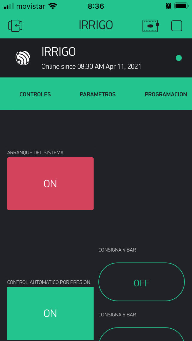
I am setting up a project to use the ttgotcall board to remotely open and close relays by gprs
My code is this


   For this example, you need to install Blynk library:
     https://github.com/blynkkk/blynk-library/releases/latest

   TinyGSM Getting Started guide:
     https://tiny.cc/tinygsm-readme

 **************************************************************

   Blynk is a platform with iOS and Android apps to control
   Arduino, Raspberry Pi and the likes over the Internet.
   You can easily build graphic interfaces for all your
   projects by simply dragging and dropping widgets.

   Blynk supports many development boards with WiFi, Ethernet,
   GSM, Bluetooth, BLE, USB/Serial connection methods.
   See more in Blynk library examples and community forum.

                  http://www.blynk.io/

   Change GPRS apm, user, pass, and Blynk auth token to run :)
 **************************************************************/

#define BLYNK_PRINT Serial    // Comment this out to disable prints and save space

// Default heartbeat interval for GSM is 60
// If you want override this value, uncomment and set this option:
// #define BLYNK_HEARTBEAT 30

// Please select the corresponding model

#define SIM800L_IP5306_VERSION_20190610
// #define SIM800L_AXP192_VERSION_20200327
// #define SIM800C_AXP192_VERSION_20200609
// #define SIM800L_IP5306_VERSION_20200811

#include "utilities.h"


// Select your modem:
#define TINY_GSM_MODEM_SIM800

// Set serial for debug console (to the Serial Monitor, default speed 115200)
#define SerialMon Serial

// Set serial for AT commands (to the module)
// Use Hardware Serial on Mega, Leonardo, Micro
#define SerialAT Serial1

// See all AT commands, if wanted
//#define DUMP_AT_COMMANDS

// Define the serial console for debug prints, if needed
#define TINY_GSM_DEBUG SerialMon

// set GSM PIN, if any
#define GSM_PIN "    ";

// Your GPRS credentials, if any
const char apn[] = "";  // search for apn of your network provider on Google
const char gprsUser[] = "";
const char gprsPass[] = "";

#include <TinyGsmClient.h>
#include <BlynkSimpleTinyGSM.h>

#ifdef DUMP_AT_COMMANDS
#include <StreamDebugger.h>
StreamDebugger debugger(SerialAT, SerialMon);
TinyGsm modem(debugger);
#else
TinyGsm modem(SerialAT);
#endif
TinyGsmClient client(modem);


// You should get Auth Token in the Blynk App.
// Go to the Project Settings (nut icon).
const char auth[] = "";


void setup()
{
  // Set console baud rate
  SerialMon.begin(115200);

 delay(1000);

  setupModem();

  SerialMon.println("Wait...");

  // Set GSM module baud rate and UART pins
  SerialAT.begin(115200, SERIAL_8N1, MODEM_RX, MODEM_TX);

  delay(6000);

  // Restart takes quite some time
  // To skip it, call init() instead of restart()
  SerialMon.println("Initializing modem...");
  modem.restart();
  // modem.init();

  String modemInfo = modem.getModemInfo();
  SerialMon.print("Modem Info: ");
  SerialMon.println(modemInfo);

  // Unlock your SIM card with a PIN
  modem.simUnlock("1234");

  Blynk.begin(auth, modem, apn, gprsUser, gprsPass);

}

void loop()
{
  Blynk.run();
 
}```


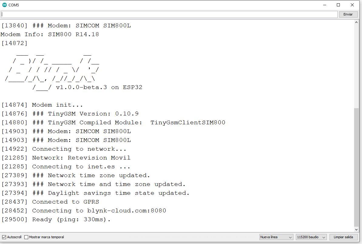
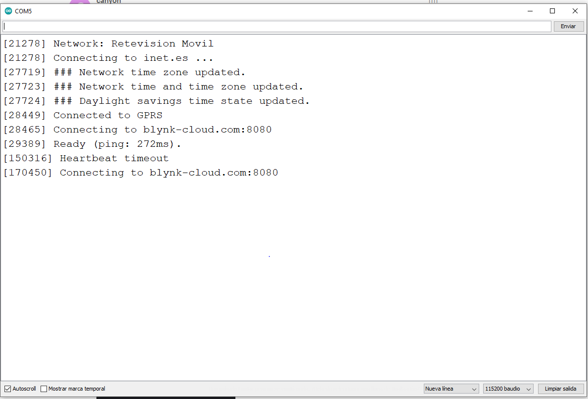
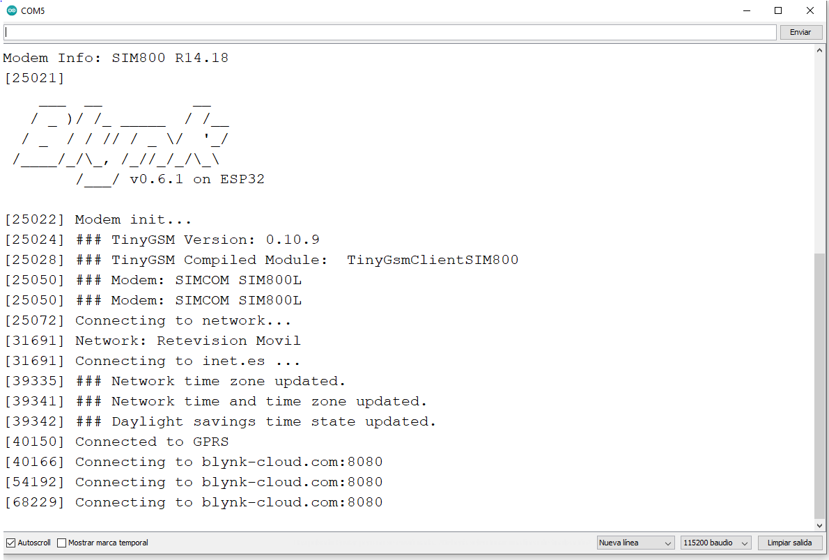
 but I can't connect to blynk-cloud,

![imagen|689x436](upload://7vOqknHTgEIlqnkyuIfToi4FbD.png) 


 what could be happening so that it doesn't connect? I have changed from port 80 to 8080 but I can't connect either
can you please help me
Thanks in advance
Greetings

@canyon please edit your post, using the pencil icon at the bottom, and add triple backticks at the beginning and end of your code so that it displays correctly.
Triple backticks look like this:
```

Pete.

Hi peter
Thanks for your quick reply, I just put the quotes

It’s funny today my project if it connects to blynk-cloud but using my app I can’t open or close the relays

but it finally disconnects


please can help me

Thanks in advance

Carlos

You’re using the beta library…

image

Remove this and install 0.6.1

Pete.

Hi Peter

I just changed the version of library and putting the port 8080

but i don’t connect

This project has a utility file also

I wonder if there could be something here that is not right

I attach it to you

It is true that I only have connected to one
push button pin 5 which is for reset
Y
pin 21 for I2C_SDA
pin 22 for I2C_SCL

then I use the GPIO 16 and 17 for the relay outputs

#include <Wire.h>

#if defined(SIM800L_IP5306_VERSION_20190610)

#define MODEM_RST             5
#define MODEM_PWRKEY          4
#define MODEM_POWER_ON       23
#define MODEM_TX             27
#define MODEM_RX             26

#define I2C_SDA              21
#define I2C_SCL              22
#define LED_GPIO             13
#define LED_ON               HIGH
#define LED_OFF              LOW

#define IP5306_ADDR          0x75
#define IP5306_REG_SYS_CTL0  0x00

// setPowerBoostKeepOn
bool setupPMU()
{
    bool en = true;
    Wire.begin(I2C_SDA, I2C_SCL);
    Wire.beginTransmission(IP5306_ADDR);
    Wire.write(IP5306_REG_SYS_CTL0);
    if (en) {
        Wire.write(0x37); // Set bit1: 1 enable 0 disable boost keep on
    } else {
        Wire.write(0x35); // 0x37 is default reg value
    }
    return Wire.endTransmission() == 0;
}


#elif defined(SIM800L_AXP192_VERSION_20200327)

#define MODEM_RST            5
#define MODEM_PWRKEY          4
#define MODEM_POWER_ON       23
#define MODEM_TX             27
#define MODEM_RX             26
#define MODEM_DTR            32
#define MODEM_RI             33

#define I2C_SDA              21
#define I2C_SCL              22
#define LED_GPIO             13
#define LED_ON               HIGH
#define LED_OFF              LOW


#elif defined(SIM800C_AXP192_VERSION_20200609)
// pin definitions
#define MODEM_PWRKEY          4
#define MODEM_POWER_ON       25
#define MODEM_TX             27
#define MODEM_RX             26
#define MODEM_DTR            32
#define MODEM_RI             33

#define I2C_SDA              21
#define I2C_SCL              22
#define LED_GPIO             12
#define LED_ON               LOW
#define LED_OFF              HIGH

#elif defined(SIM800L_IP5306_VERSION_20200811)


#define MODEM_RST             5
#define MODEM_PWRKEY          4
#define MODEM_POWER_ON       23
#define MODEM_TX             27
#define MODEM_RX             26

#define MODEM_DTR            32
#define MODEM_RI             33

#define I2C_SDA              21
#define I2C_SCL              22
#define LED_GPIO             13
#define LED_ON               HIGH
#define LED_OFF              LOW

#define IP5306_ADDR          0x75
#define IP5306_REG_SYS_CTL0  0x00

// setPowerBoostKeepOn
bool setupPMU()
{
    bool en = true;
    Wire.begin(I2C_SDA, I2C_SCL);
    Wire.beginTransmission(IP5306_ADDR);
    Wire.write(IP5306_REG_SYS_CTL0);
    if (en) {
        Wire.write(0x37); // Set bit1: 1 enable 0 disable boost keep on
    } else {
        Wire.write(0x35); // 0x37 is default reg value
    }
    return Wire.endTransmission() == 0;
}

#else

#error "Please select the corresponding model"

#endif


#if defined(SIM800L_AXP192_VERSION_20200327) || defined(SIM800C_AXP192_VERSION_20200609)
#include <axp20x.h>         //https://github.com/lewisxhe/AXP202X_Library

AXP20X_Class axp;

bool setupPMU()
{
// For more information about the use of AXP192, please refer to AXP202X_Library https://github.com/lewisxhe/AXP202X_Library
    Wire.begin(I2C_SDA, I2C_SCL);
    int ret = axp.begin(Wire, AXP192_SLAVE_ADDRESS);

    if (ret == AXP_FAIL) {
        Serial.println("AXP Power begin failed");
        return false;
    }

    //! Turn off unused power
    axp.setPowerOutPut(AXP192_DCDC1, AXP202_OFF);
    axp.setPowerOutPut(AXP192_LDO2, AXP202_OFF);
    axp.setPowerOutPut(AXP192_LDO3, AXP202_OFF);
    axp.setPowerOutPut(AXP192_DCDC2, AXP202_OFF);
    axp.setPowerOutPut(AXP192_EXTEN, AXP202_OFF);

    //! Do not turn off DC3, it is powered by esp32
    // axp.setPowerOutPut(AXP192_DCDC3, AXP202_ON);

    // Set the charging indicator to turn off
    // Turn it off to save current consumption
    // axp.setChgLEDMode(AXP20X_LED_OFF);

    // Set the charging indicator to flash once per second
    // axp.setChgLEDMode(AXP20X_LED_BLINK_1HZ);


    //! Use axp192 adc get voltage info
    axp.adc1Enable(AXP202_VBUS_VOL_ADC1 | AXP202_VBUS_CUR_ADC1 | AXP202_BATT_CUR_ADC1 | AXP202_BATT_VOL_ADC1, true);

    float vbus_v = axp.getVbusVoltage();
    float vbus_c = axp.getVbusCurrent();
    float batt_v = axp.getBattVoltage();
    // axp.getBattPercentage();   // axp192 is not support percentage
    Serial.printf("VBUS:%.2f mV %.2f mA ,BATTERY: %.2f\n", vbus_v, vbus_c, batt_v);

    return true;
}

#endif


void setupModem()
{

    // Start power management
    if (setupPMU() == false) {
        Serial.println("Setting power error");
    }

#ifdef MODEM_RST
    // Keep reset high
    pinMode(MODEM_RST, OUTPUT);
    digitalWrite(MODEM_RST, HIGH);
#endif

    pinMode(MODEM_PWRKEY, OUTPUT);
    pinMode(MODEM_POWER_ON, OUTPUT);

    // Turn on the Modem power first
    digitalWrite(MODEM_POWER_ON, HIGH);

    // Pull down PWRKEY for more than 1 second according to manual requirements
    digitalWrite(MODEM_PWRKEY, HIGH);
    delay(100);
    digitalWrite(MODEM_PWRKEY, LOW);
    delay(1000);
    digitalWrite(MODEM_PWRKEY, HIGH);

    // Initialize the indicator as an output
    pinMode(LED_GPIO, OUTPUT);
    digitalWrite(LED_GPIO, LED_OFF);
}

You should probably try a different SIM card, from a different mobile operator.
Your current operator may be blocking the Blynk data on port 8080

Pete.

Hi Peter
Good Morning
Yes, I have changed SIM card and then it has connected
Thank you very much for your help,

I continue with my porject if I have any further questions I will consult you

Thanks again

Greetings

1 Like