Hello everyone,
I have a simple question for you:
In My project I have a button that change ON / OFF realy, so my button control a digital pin that link my relay. After, I add a timer to do the same…now why should I use virtual pin to use timer? By widget button I don’t use skecth and virtual pin, I use only digital pin and works, why isn’t the same? In my project I use button to turn on and off a light (I don’t use sketch and virtual pin, blynk provide to work all). If I use also a timer why doesn’t work? Thank you
Andrea
The time widget does allow this (at least on iOS anyway)
The time input widget doesn’t.
Which widget did you actually try?
I have IOs and my widget is a simple timer.
Please see my photo. I have two button with two timer. The button I use only to stop relay if I want.
let me know
Thank you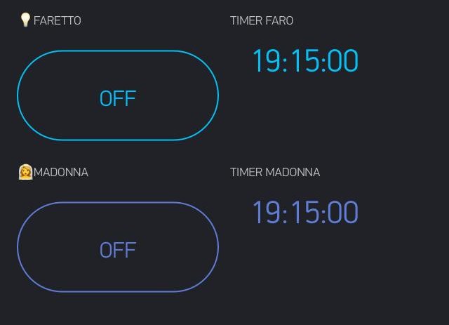
The Timer widget in iOS does allow either digital or virtual pins to be selected.
Personally, I never use digital pins, virtual pins are much more powerful.
But, what exactly is your question?
Pete.
Actually, my timer works only for start, stop doesn’t work.
At start timer, my relay becomes ON and relative button becomes ON.
So far is good, but at the end of timer nothing happens! Why?
Thank you
I think you need to effectively start again with this tread.
Start by providing the basic info about what hardware and Blynk library version you are using, along with a summary of exactly what it is that you’re trying to achieve and why this inst working.
Share the code that you’re using - correctly formatted with triple backticks at the beginning and end.
Triple backticks look like this:
```
Also share details of what you have set-up in your app - what widgets you have, what pins they are connected to, and what their purpose is.
Pete.
And also the settings of the button and timer widget.
I have just tried this (albeit with a virtual pin) but the timer triggered both on and off for my button. (I guess like you want)
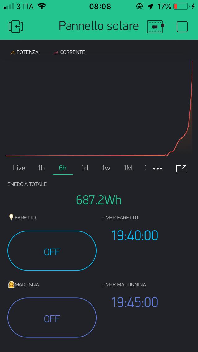
My project works to control the energy of my solar panel.
I use NodeMcu, current sensor INA219 and relay 4ch.
My 2 button set on D5 and D6 simply.
Before timer, I use normally, start and stop without problem.
Actually with 2 timer, only works only start!
Do you need other?
Thank you
SORRY…
#include <Blynk.h>

#include <Wire.h>
#include <Adafruit_INA219.h>
#define BLYNK_PRINT Serial


#include <ESP8266WiFi.h>
#include <BlynkSimpleEsp8266.h>

char auth[] = "xxxxxxx";

Adafruit_INA219 ina219;

// Your WiFi credentials.
// Set password to "" for open networks.

char ssid[] = "xxxxxxxxxxx";
char pass[] = "xxxxxx";

//char ssid[] = "xxxxxx";
//char pass[] = "xxxxxx?";

float shuntvoltage = 0;
float busvoltage = 0;
float current_mA = 0;
float loadvoltage = 0;
float power_mW = 0;
float energy = 0;

unsigned long previousMillis = 0;
unsigned long interval = 100;
unsigned long currentMillis = 0;

#define greenLED D7
#define redLED D8


BlynkTimer timer;

// This function sends Arduino's up time every second to Virtual Pin (5).
// In the app, Widget's reading frequency should be set to PUSH. This means
// that you define how often to send data to Blynk App.


void setup(void) {

  // Debug console
  Serial.begin(9600);

  Blynk.begin(auth, ssid, pass);

  pinMode(greenLED, OUTPUT);
  pinMode(redLED, OUTPUT);

  // Setup a function to be called every second
  timer.setInterval(1000L, myTimerEvent);
  Serial.begin(115200);

  while (!Serial) {
      // will pause Zero, Leonardo, etc until serial console opens
     delay(1);
  }

  uint32_t currentFrequency;


  ina219.begin();
  // To use a slightly lower 32V, 1A range (higher precision on amps):
  //ina219.setCalibration_32V_1A();
  // Or to use a lower 16V, 400mA range (higher precision on volts and amps):
  //ina219.setCalibration_16V_400mA();

 // Serial.println("Measuring voltage and current with INA219 ...");
}

void loop(void){


  if(Blynk.connected()){  // not to be confused with BLYNK_CONNECTED()

    digitalWrite(greenLED, HIGH);
    digitalWrite(redLED, LOW);
    //Serial.print("CONNESSO");

    currentMillis = millis();

    if (currentMillis - previousMillis >= interval){
      previousMillis = currentMillis;
      ina219values();
     // stampaValori();
      Blynk.run();
      timer.run(); // Initiates BlynkTimer
    }

  }else{

    digitalWrite(greenLED, LOW);
    digitalWrite(redLED, HIGH);

   // Serial.print("NON CONNESSO");


    Blynk.begin(auth, ssid, pass);
  }

  delay(1000);
}


void ina219values() {
  shuntvoltage = ina219.getShuntVoltage_mV();
  busvoltage = ina219.getBusVoltage_V();
  current_mA = ina219.getCurrent_mA();
  if (current_mA<0){
    current_mA = current_mA*(-1);
  }
  power_mW = ina219.getPower_mW();
  loadvoltage = busvoltage + (shuntvoltage / 1000);
  energy = energy + loadvoltage * current_mA / 3600;
}

void stampaValori(){
  Serial.print("Bus Voltage:   "); Serial.print(busvoltage); Serial.println(" V");
  Serial.print("Shunt Voltage: "); Serial.print(shuntvoltage); Serial.println(" mV");
  Serial.print("Load Voltage:  "); Serial.print(loadvoltage); Serial.println(" V");
  Serial.print("Current:       "); Serial.print(current_mA); Serial.println(" mA");
  Serial.print("Power:         "); Serial.print(power_mW); Serial.println(" mW");
  Serial.print("Energia:         "); Serial.print(energy); Serial.println(" mWh");
  Serial.println("");
}


void myTimerEvent(){
  // You can send any value at any time.
  // Please don't send more that 10 values per second.
  Blynk.virtualWrite(V4, current_mA / 1000);
  Blynk.virtualWrite(V5, power_mW / 1000);
  Blynk.virtualWrite(V6, energy / 1000);
}Despite me saying this:
you still posted your code without the triple backticks, so your unformatted code has been removed.
Please edit your last post, using the pencil icon at the bottom of the post, and add-in your code - complete with backticks.
Pete.
Sorry, now I rewrite my post
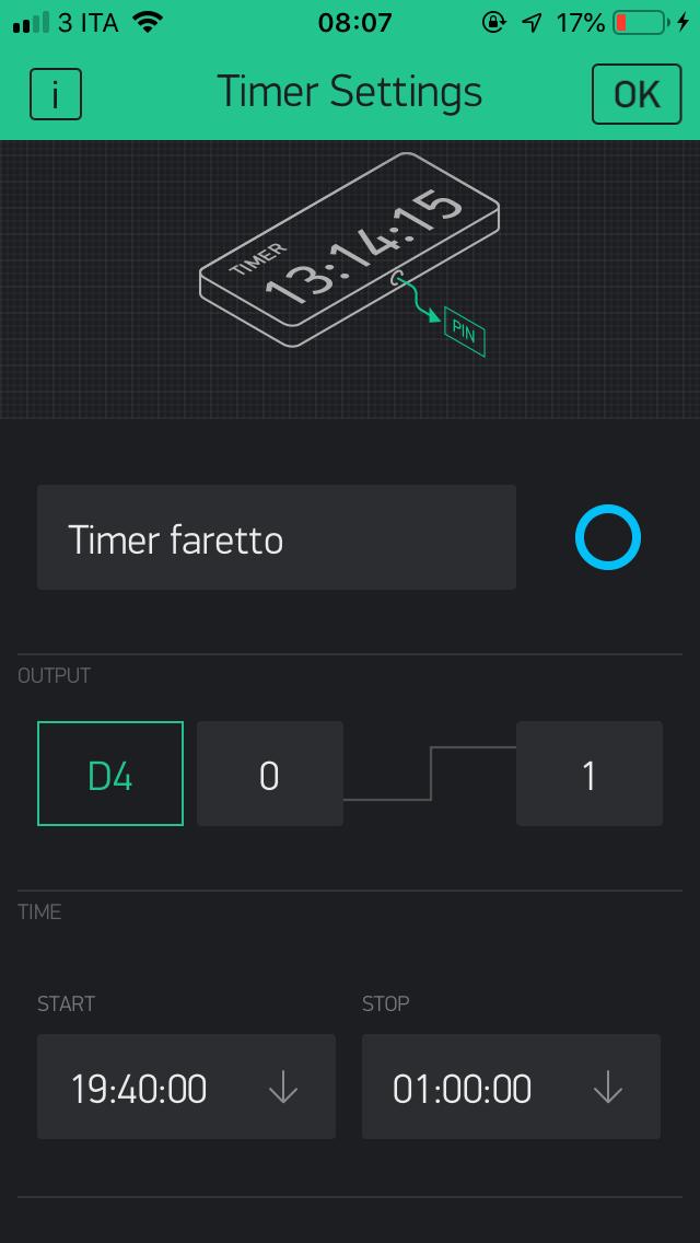
And how are your timer widgets configured?
Pete.
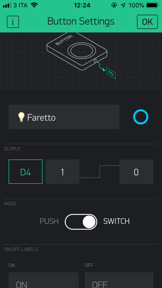
So in your app you appear to have the following:
One timer widget *(called Faro or Faretto, depending on which screenshot we are looking at) that is connected to pin D4
You have another timer widget (called Madonna) connected to an unknown pin
You have a switch widget (called Faretto) connected to D5 or D6
You have a switch widget (called Madonna) connected to D5 or D6
Can you please clarify the missing information for these widget pins, and explain how the timer on/off switch widgets are able to override the timers when they are connected to different digital pins to the timer widgets?
Pete.
Faretto and Timer Faretto on D4
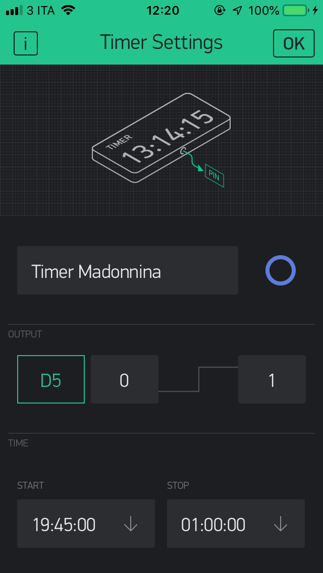
Madonna and Timer Madonna on D5
In This photo you CAn see setting of Timer madonna
Thank you
I don’t know if this time I was clear…
Button D4 and Timer D4 control the same relay (Faretto light)
Button D5 and Timer D5 control the same relay (Madonna light)
The buttons I would use only if I want to stop light when I want (in the case one day I had to accumulate little solar energy).
Timers I would use to start light automatically.
Thank you
It’s been painfully difficult extracting the correct information from you about the setup of 4 simple widgets!
If these widgets are configured in the way that you’ve said in your latest post (which conflicts with what you said earlier) then they should probably work correctly - but, as I don’t use digital pins, or the timer widget, my personal experience in this area is limited.
However, as I said earlier, virtual pins are much more appropriate for this type of application and that’s the way that I’d go if I were you.
Pete.
sorry, but what’s so difficult?
1° Realy on D4 actived by Timer1 (also started and stopped by Button1)
2° Realy on D5 actived by Timer2 (also started and stopped by Button2)
D4 and D5 are digital pin
Can timer active and stop digital pin??
In my case, stop doesn’t work, works only button widget.
simpler than that?
Thank you
I’d say that any time you have multiple widgets trying to control the same pins then you’re asking for problems.
You may also have multiple things trying to control the same pins, because you’re using mixed referencing for the pin numbers, and it’s also not clear how your current sensor is wired.
But, the bottom line is that your current setup isn’t working.
Pete.