Hello everyone, I am an esp32 newbie and I am working on a smart water tank project. Let me introduce:
Source Code
#define BLYNK_PRINT Serial
#define BLYNK_TEMPLATE_ID "TMPL6v9JuHYAV"
#define BLYNK_TEMPLATE_NAME "Smart Water Tank"
#define BLYNK_AUTH_TOKEN "VRd-62sso0mg1tDc214HyxoMrXbvr8Og"
#include <WiFi.h>
#include <WiFiClient.h>
#include <BlynkSimpleEsp32.h>
#include <LiquidCrystal_I2C.h>
int lcdColumns = 16;
int lcdRows = 2;
int MQ7sensorPin = 15;
int MQ135sensorPin = 13;
int MQ7sensorData;
int MQ135sensorData;
LiquidCrystal_I2C lcd(0x27, lcdColumns, lcdRows);
BlynkTimer timer;
char auth[] = "VRd-62sso0mg1tDc214HyxoMrXbvr8Og";
char ssid[] = "LINKSYS";
char pass[] = "ab123456";
void sendSensor()
{
Blynk.virtualWrite(V0,MQ7sensorData);
Blynk.virtualWrite(V1,MQ135sensorData);
}
void setup()
{
lcd.init(); // initialize LCD
lcd.backlight(); // turn on LCD backlight
Serial.begin(115200);
Blynk.begin(auth, ssid, pass);
pinMode(MQ7sensorPin,INPUT);
pinMode(MQ135sensorPin,INPUT);
timer.setInterval(1000L, sendSensor);
}
void loop()
{
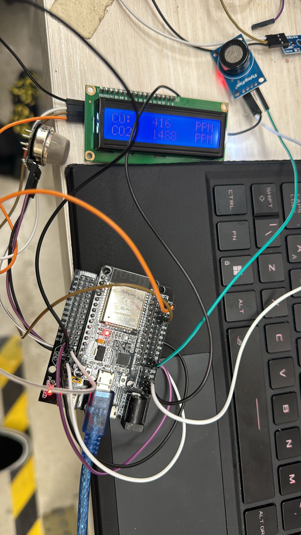
MQ7sensorData = analogRead(MQ7sensorPin);
lcd.setCursor(0,0);
lcd.print("CO:");
lcd.setCursor(6,0);
lcd.print(MQ7sensorData);
lcd.setCursor(13,0);
lcd.println("PPM");
MQ135sensorData = analogRead(MQ135sensorPin);
lcd.setCursor(0,1);
lcd.print("CO2:");
lcd.setCursor(6,1);
lcd.print(MQ135sensorData);
lcd.setCursor(13, 1);
lcd.println("PPM");
delay(1000);
Blynk.run();
timer.run();
}
The problem is when I // Blynk.begin(auth, ssid, pass); and //Blynk.run (); , IC2 BORAD can display the data.
When I add these two pieces of code to the program, it just displays 0 on the i2c board.
How to fix it? thank you all
You can’t use ADC2 pins at the same time as WiFi.
Read this, and also take note of the “keep your void loop clean” comments too…
A few comments from me…
This code is redundant if you are using Blynk.begin()…
You are using GPIO5 as an analog input…
but GPIO5 is not connect to an Analog to Digital Converter (ADC) in tge ESP32 chip. You need to use one of the GPIO pins that is connected to ADC1 (Because the ADC2 pins can’t be used at the same time was WiFi). ADC1 pins are…
ADC1_CH0 (GPIO 36)
ADC1_CH1 (GPIO 37)
ADC1_CH2 (GPIO 38)
ADC1_CH3 (GPIO 39)
ADC1_CH4 (GPIO 32)
ADC1_CH5 (GPIO 33)
ADC1_CH6 (GPIO 34)
ADC1_CH7 (GP…
Pete.
So, is this the new program?
#define BLYNK_PRINT Serial

#define BLYNK_TEMPLATE_ID "TMPL6v9JuHYAV"
#define BLYNK_TEMPLATE_NAME "Smart Water Tank"
#define BLYNK_AUTH_TOKEN "VRd-62sso0mg1tDc214HyxoMrXbvr8Og"

#include <WiFi.h>
#include <WiFiClient.h>
#include <BlynkSimpleEsp32.h>

#include <LiquidCrystal_I2C.h>

int lcdColumns = 16;
int lcdRows = 2;

LiquidCrystal_I2C lcd(0x27, lcdColumns, lcdRows);

BlynkTimer timer;

char auth[] = "VRd-62sso0mg1tDc214HyxoMrXbvr8Og";
char ssid[] = "LINKSYS";
char pass[] = "ab123456";


void sendSensor()
{
  int MQ7sensorData = analogRead(15);
  Blynk.virtualWrite(V0, MQ7sensorData);
  int MQ135sensorData = analogRead(13);
  Blynk.virtualWrite(V1, MQ135sensorData);

  lcd.setCursor(0,0);
  lcd.print("CO:");
  lcd.setCursor(6,0);
  lcd.print(MQ7sensorData);
  lcd.setCursor(13,0);
  lcd.println("PPM");

  lcd.setCursor(0,1);
  lcd.print("CO2:");
  lcd.setCursor(6,1);
  lcd.print(MQ135sensorData);
  lcd.setCursor(13, 1);
  lcd.println("PPM");
  delay(1000);
}


void setup()
{
  lcd.init();    // initialize LCD
  lcd.backlight();     // turn on LCD backlight

  Serial.begin(115200);
  Blynk.begin(auth, ssid, pass);

  pinMode(15,INPUT);
  pinMode(13,INPUT);


  timer.setInterval(1000L, sendSensor);

}

void loop()
{
  Blynk.run();
  timer.run();
}
I’ve been trying but it doesn’t work, it keeps showing 0
You’re still using the same ADC2 pins. You need to swap your sensors to ADC1 pins and update your sketch.
Pete.
It works, thank you so much!!