Template not showing up in Developer mode in Blynk App

Hi,
Newbie here hope you could help me please.

I created a template online (web dashboard). Next up to my mobile to add new device. Went to Developer mode but the template i created on web dashboard not showing up.

Unable to add new device (a ESP32 in use)

Thanks

You seem to be getting confused between templates and devices.

You can have multiple devices based on the same template. I guess that in the web console you’ve created a device and are attempting to create the same device in the app.

Devices tgat you create in either the web console or the app should automatically appear on both the app and web console.

Pete.

Hi Pete,

Thanks.

I created another template on web and it appears on my mobile developer mode.

However, I still unable to add new device on the app?

I was following a youtube to get started but sadly stuck here. Circa 10 min to add new device.

Okay, so you’re using the Edgent example?
It would have been good if you’d said that in post #1

What does your serial monitor say?
Please copy the serial monitor text and paste it here with triple backticks at the beginning and end.
Triple backticks look like this:
```

Pete.

Hi Pete,
Thanks again for helping.
I am not using Edgent. I went to examples.blynk.cc for ESP32 example code and with necessary amendment.

I think Device setup between Blynk web and my mobile app is ok. Both communicating - switch on/off.

17:05:26.674 -> ets Jul 29 2019 12:21:46
17:05:26.674 -> 
17:05:26.674 -> rst:0x1 (POWERON_RESET),boot:0x13 (SPI_FAST_FLASH_BOOT)
17:05:26.674 -> configsip: 0, SPIWP:0xee
17:05:26.674 -> clk_drv:0x00,q_drv:0x00,d_drv:0x00,cs0_drv:0x00,hd_drv:0x00,wp_drv:0x00
17:05:26.710 -> mode:DIO, clock div:1
17:05:26.710 -> load:0x3fff0030,len:1412
17:05:26.710 -> load:0x40078000,len:13400
17:05:26.710 -> load:0x40080400,len:3672
17:05:26.710 -> entry 0x400805f8
17:05:27.005 -> [22] Connecting to AndroidAP
17:06:04.620 -> [37637] Connected to WiFi
17:06:04.620 -> [37637] IP: 192.168.102.140
17:06:04.620 -> [37637] 
17:06:04.620 ->     ___  __          __
17:06:04.620 ->    / _ )/ /_ _____  / /__
17:06:04.620 ->   / _  / / // / _ \/  '_/
17:06:04.620 ->  /____/_/\_, /_//_/_/\_\
17:06:04.620 ->         /___/ v1.1.0 on ESP32
17:06:04.620 -> 
17:06:04.620 ->  #StandWithUkraine    https://bit.ly/swua
17:06:04.620 -> 
17:06:04.620 -> 
17:06:04.620 -> [37648] Connecting to blynk.cloud:80
17:06:05.425 -> [38466] Ready (ping: 203ms).

I am using firebeetle ESP32E. I tried their initial setup runs, they are working ok. E.g. 7.4 WiFi Tutorial
https://wiki.dfrobot.com/FireBeetle_Board_ESP32_E_SKU_DFR0654#target_6

What do you think? Just couldn’t switch on the LED on pin 21?

Below are the code.

https://examples.blynk.cc/?board=ESP32&shield=ESP32%20WiFi&example=GettingStarted%2FBlynkBlink

with some modifications specific to 

#define BLYNK_TEMPLATE_ID "TMPL5MbBfajw"
#define BLYNK_DEVICE_NAME "Pump"
#define BLYNK_AUTH_TOKEN "qomzR-yr--UoKmDgo75ClzqPz9bMJOUl"


// Comment this out to disable prints and save space
#define BLYNK_PRINT Serial


#include <WiFi.h>
#include <WiFiClient.h>
#include <BlynkSimpleEsp32.h>

char auth[] = BLYNK_AUTH_TOKEN;

// Your WiFi credentials.
// Set password to "" for open networks.
char ssid[] = "AndroidAP";
char pass[] = "H1100";

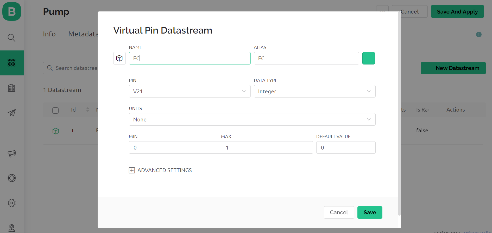
BLYNK_WRITE(V21)  // this is the pin where LED on 21
{
  int s0 = param.asInt();
  if (s0 == HIGH);
  {
    digitalWrite(21, HIGH);
  }
  if (s0 == LOW);
  {
    digitalWrite(21, LOW);
  }
}
void setup()
{
  // Debug console
  Serial.begin(115200);
  pinMode (21, OUTPUT);
  digitalWrite(21, HIGH);    // This added to check if LED light on? But no...
  
  //Blynk.begin(auth, ssid, pass);
  // You can also specify server:
  Blynk.begin(auth, ssid, pass, "blynk.cloud", 80);    // Using this here
  //Blynk.begin(auth, ssid, pass, IPAddress(192,168,1,100), 8080);
}

void loop()
{
  Blynk.run();
  }

In that case, I’m confused about the relevance of the video that you linked to. The provisioning process shown at the 10 minute mark relates ONLY to Edgent, and the sketch used in the video is the Edgent sketch.

Your device is connecting to Blynk successfully, so there is no need to follow the provisioning process shown at the 10 minute mark in the video.

I’m guessing that you’ve chosen virtual pin 21 in Blynk as you believe that this is somehow linked to pin 21 on your board? That isn’t the case, any virtual pin can be used to control any physical pin - or multiple physical pins at the same time if you wish.

How have you configured the V21 datastream in the Blynk web browser, and how have you configured the switch widget that you are using?

How is your LED wired? You’ve said that one side is connected to physical pin 21, but where is the other side connected?
Are you using a current limiting resistor with your LED, and are you certain that the you have the polarity correct?

Pete.

Hi Pete,
I got the ESP32 connected. 1st hurdle cleared.

17:25:30.897 -> [2637] IP: 192.168.102.140
17:25:30.897 -> [2637] 
17:25:30.897 ->     ___  __          __
17:25:30.897 ->    / _ )/ /_ _____  / /__
17:25:30.897 ->   / _  / / // / _ \/  '_/
17:25:30.897 ->  /____/_/\_, /_//_/_/\_\
17:25:30.897 ->         /___/ v1.1.0 on ESP32
17:25:30.897 -> 
17:25:30.897 ->  #StandWithUkraine    https://bit.ly/swua
17:25:30.897 -> 
17:25:30.897 -> 
17:25:30.897 -> [2648] Connecting to blynk.cloud:80
17:25:31.378 -> [3118] Ready (ping: 203ms).
17:28:50.018 -> ets Jul 29 2019 12:21:46
17:28:50.018 -> 
17:28:50.018 -> rst:0x1 (POWERON_RESET),boot:0x13 (SPI_FAST_FLASH_BOOT)
17:28:50.018 -> configsip: 0, SPIWP:0xee
17:28:50.018 -> clk_drv:0x00,q_drv:0x00,d_drv:0x00,cs0_drv:0x00,hd_drv:0x00,wp_drv:0x00
17:28:50.018 -> mode:DIO, clock div:1
17:28:50.018 -> load:0x3fff0030,len:1412
17:28:50.018 -> load:0x40078000,len:13400
17:28:50.018 -> load:0x40080400,len:3672
17:28:50.018 -> entry 0x400805f8
17:28:50.338 -> [23] Connecting to AndroidAP
17:30:10.868 -> [22] Connecting to AndroidAP
17:30:13.473 -> [2635] Connected to WiFi
17:30:13.473 -> [2635] IP: 192.168.102.140
17:30:13.473 -> [2635] 
17:30:13.473 ->     ___  __          __
17:30:13.473 ->    / _ )/ /_ _____  / /__
17:30:13.473 ->   / _  / / // / _ \/  '_/
17:30:13.473 ->  /____/_/\_, /_//_/_/\_\
17:30:13.473 ->         /___/ v1.1.0 on ESP32
17:30:13.473 -> 
17:30:13.473 ->  #StandWithUkraine    https://bit.ly/swua
17:30:13.473 -> 
17:30:13.473 -> 
17:30:13.473 -> [2646] Connecting to blynk.cloud:80
17:30:14.319 -> [3462] Ready (ping: 204ms).

Same program as above, the LED on. But here comes another issue? I pressed the switch on/off (once) - the LED turned off.  But subsequently unable to take further command from either wed or app.

I feel that I need to add new device (the esp32?).  What do you think?

Thanks again.

Hi Pete,
TIA! Here are the answers you’re after. Still unsure where went wrong.

  1. Only able to turn on/off once after loading.
  2. Press reset button after to no success. Need to reload the program to go back to problem 1.(above)?

in the template > virtual pin datastream > NAME: EC / PIN: V21

web dashboard > control: switch; Switch setting: data stream: EC(V21)

in the IDE program, [apologies - some minor modifications to the LED pin]

int pin = D2; // define where the LED+ wired to D2 on the firebeetle D2 (next to TX) and LED- to GND (polarity checked). Not using resistor (3.3v)

[Unformatted code removed by moderator]

@SL145585 Please edit your post and put triple backticks at the beginning and end of your code so that it displays correctly.

I’d also suggest that you post your entire updated sketch, not simply code snippets.

Pete.

Hi Pete,
My bad. Sorry. Let’s start over.

in the template > virtual pin datastream > NAME: EC / PIN: V21

web dashboard > control: switch; Switch setting: data stream: EC(V21)

  1. Connected Wifi. LED ON.
  2. Only able to turn on/off once after loading.
  3. Press reset button after to no success. Need to reload the program to go back to problem 2.(above)?

Do you think I need to add new device (the firebeetle esp32) as per youtube to get it working properly? I still couldn’t add new device with my mobile. Unable to find device.

I feel we are getting there but not quite. Thanks.


  You’ll need:
   - Blynk IoT app (download from App Store or Google Play)
   - ESP32 board
   - Decide how to connect to Blynk
     (USB, Ethernet, Wi-Fi, Bluetooth, ...)

  There is a bunch of great example sketches included to show you how to get
  started. Think of them as LEGO bricks  and combine them as you wish.
  For example, take the Ethernet Shield sketch and combine it with the
  Servo example, or choose a USB sketch and add a code from SendData
  example.
 *************************************************************/

// Template ID, Device Name and Auth Token are provided by the Blynk.Cloud
// See the Device Info tab, or Template settings
#define BLYNK_TEMPLATE_ID "TMPL5MbBfajw"
#define BLYNK_DEVICE_NAME "Pump"
#define BLYNK_AUTH_TOKEN "qomzR-yr--UoKmDgo75ClzqPz9bMJOUl"


// Comment this out to disable prints and save space
#define BLYNK_PRINT Serial


#include <WiFi.h>
#include <WiFiClient.h>
#include <BlynkSimpleEsp32.h>

char auth[] = BLYNK_AUTH_TOKEN;

// Your WiFi credentials.
// Set password to "" for open networks.
char ssid[] = "AndroidAP";
char pass[] = "xxx123";

int pin        = D2;

BLYNK_WRITE(V21)
{
  int s0 = param.asInt();
  if (s0 == HIGH);
  {
    digitalWrite(pin, HIGH);
  }
  if (s0 == LOW);
  {
    digitalWrite(pin, LOW);
  }
}
void setup()
{
  // Debug console
  Serial.begin(115200);
  pinMode (pin, OUTPUT);
  digitalWrite(pin, HIGH);
  
  //Blynk.begin(auth, ssid, pass);
  // You can also specify server:
  Blynk.begin(auth, ssid, pass, "blynk.cloud", 80);
  //Blynk.begin(auth, ssid, pass, IPAddress(192,168,1,100), 8080);
}

void loop()
{
  Blynk.run();
  // You can inject your own code or combine it with other sketches.
  // Check other examples on how to communicate with Blynk. Remember
  // to avoid delay() function!
}

Okay, so you’re using the onboard LED connected to GPIO2.

The LED will be active LOW, so lit when GPIO2 is pulled LOW.

This line in your void setup:

is turning the LED on at start up.

This doesn’t tell me what I need to know. Either post a screenshot, or list each parameter in the Virtual Pin Datastream screen.

Are you using a phone access point for this?
If so, do you have a domestic WiFi network that you can connect to instead - at least for testing?

Pete.

Hi Pete,

I am using my mobile hotspot. Local work wifi (probably blocked) unable to connect.

Can you change this part of your sketch:

to this:

int ledPin        = 2;

BLYNK_WRITE(V21)
{
  if (param.asInt());
  {
    digitalWrite(ledPin, LOW);
  }
  else
  {
    digitalWrite(ledPin, HIGH);
  }
}

and these lines in your void setup:

to this:

  pinMode (ledPin, OUTPUT);
  digitalWrite(ledPin, LOW);

This has done three things:

  1. Referenced the LED as GPIO 2, not D2 (it should have been D9 according to the link)
  2. Given your pin variable a more meaningful name, and avoided any possible keyword conflicts
  3. Swapped your LOW/HIGH logic around to make it work with an Active LOW LED

Pete.

Compile error.
‘else’ without a previous ‘if’

Just remove the semicolon. It should look like this

BLYNK_WRITE(V21)
{
  if (param.asInt())
  {
    digitalWrite(ledPin, LOW);
  }
  else
  {
    digitalWrite(ledPin, HIGH);
  }
}

Hi Pete, John93

Good news finally.

Connected with mobile hotspot.

Pete’s code LED was referring to the builtin led on the esp32.

The switch on both web and app able to turn on and off.

I shall try another pin with another led. Thanks.

Thanks @John93!
I usually forget them, but then add them where they shouldn’t be!

Pete.

1 Like

Gents,

Thanks heaps. I added another LED and both working like magic!

Much appreciated.