Project Description
To collect data from the ponds such as Dissolved Oxygen Level, PH, temperature and TDS. Also, these parameters value will be displayed on Blynk console. Now depending upon the value of DO level, a particular ESP32 node(child node) should be able to trigger a starter motor which works on 3 phase. Although this will be at later stage.
Components
• ESP32 WROOM DA Module
• DO sensor View Reference
• Temperature Sensor View Reference
• PH Sensor View Reference
• TDS senor (yet to implement)
You can reference my previous post for more details here
For now I am focusing on getting all readings for Single Child Node. That is from one child node I should get some parameters and it all should be displayed on my Blynk app!
Here are the Parameters which I am looking for:
- Dissolved Oxygen Level
- PH
- Temperature
- TDS
Now, I am able to get the values of Temperature and PH Level (with some minor difference due to Calibration Issue I guess) but facing issues to get some correct reference for DO(Dissolved Oxygen) and due to which I am not able to get readings for DO level.
Here is the Blynk console:
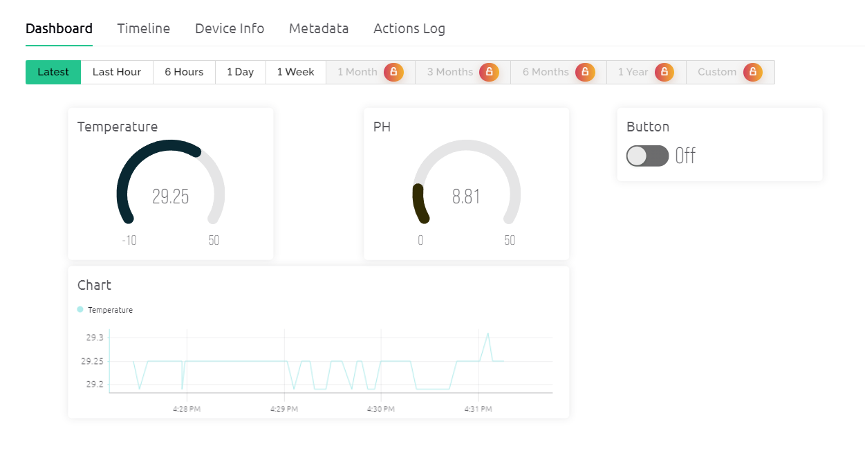
I may add DO and TDS widget later once their implementation is working! If anyone is curious about that button, so that button is to showcase how from Blynk App I can try to trigger something. Like, since now I focusing on only one child node, when the button is triggered, the serial monitor will get a statement of Motor 1 is ON. Also, one of the variable in the code of Child Node serves as the status which specifies that that particular child node is triggered. Although it’s not completely working fine but it’s a simulation type for triggering Motor Purpose. I have thought to use a 4 Channel Relay Module to trigger the motor depending upon the Child Node’s input. (Please don’t get confuse with this as this post is not seeking help for implementing the triggering purpose, Thanks!)
So is there anyone who have worked on similar projects or have any idea about this? Help is Appreciated.
For now, My requirement is to get the DO and TDS readings. So since the temperature and ph sensors are used with ESP32, I expect the same from DO and TDS as well.
Below are some references I tried:
-
DO with Arduino
I tried this, followed all procedure of adding KCL and attaching Membrane, and edited the code for DO as well still didn’t work, like there is no change in reading for different quality of water, also I tried this using only Arduino but still there was no change in reading -
DO sensor of DF ROBOT
We haven’t bought this sensor as it is expensive, although some part is similar as it is also a DO sensor
As you have seen DO sensors are available 2 types, I preferred to use first as it comes in my Budget.
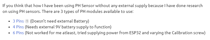
If you think that how I have been using PH Sensor without any external supply because I have done research on using PH sensors. There are 3 types of PH modules available to use:
- 3 Pins (Doesn’t need external Battery)
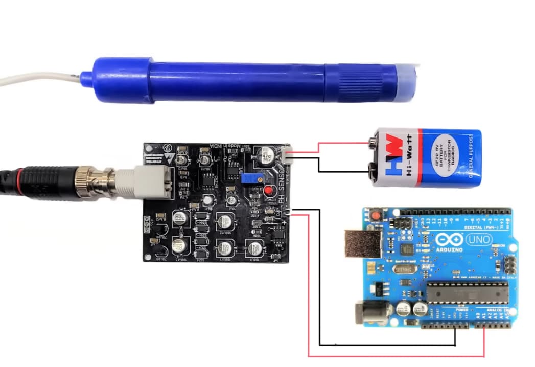
- 4 Pins (Needs external 9V battery supply to function)
- 6 Pins (Not worked for me atleast, tried supplying power from ESP32 and varying the Calibration screw)
Now among all the PH modules, the 3 pins suits for my project as it doesn’t needs an external Battery supply. Just one thing is issue for me is that the PH values are varying even after calibrating the sensor (Done calibration on Normal Water to bring PH to 7). Don’t know the exact issue, if anyone knows then help will be appreciated!
Also, I need as some advice to power all the boards, like what would be easy to implement and cost effective solution for the power management in the system.
I will attach all the codes that I have used for a Single Node Child (with Gateway and Blynk Code)
Code for Blynk Node(which sends Data to Cloud and is connected to Internet)
#define BLYNK_PRINT Serial

// Blynk's Credentials
#define BLYNK_TEMPLATE_ID "ID_here"
#define BLYNK_TEMPLATE_NAME "Project"
#define BLYNK_AUTH_TOKEN "TOKEN_here"

// Necessary Libraries
#include <WiFi.h>
#include <WiFiClient.h>
#include <BlynkSimpleEsp32.h>
#include <ArduinoJson.h>

// Serial2 pins of ESP32
#define RXD2 16
#define TXD2 17

char auth[] = BLYNK_AUTH_TOKEN;

// Your WiFi credentials.
char ssid[] = "iot";
char pass[] = "123456789";

// Variables
int board;
int pin;
bool pin_status;
String message = "";
bool messageReady = false;
double child1_temperature;
double child1_ph;


#define LED_PIN 2  // LED is usually connected to D2 pin. Change if needed.

// BLYNK_WRITE(V0) {
//   board = 0;
//   pin = LED_PIN;
//   pin_status = param.asInt();  // Pin Status 1/0
//   Serial.println("V0 On");
// }


// Data Coming from Blynk App
BLYNK_WRITE(V3) {
  board = 1;
  pin = LED_PIN;
  pin_status = param.asInt();  // Pin Status 1/0
  //Serial.println(pin_status);
  if(pin_status == 1){
    Serial.println("Motor 1 On");
  }else{
    Serial.println("Motor 1 Off");
  }
}

// BLYNK_WRITE(V2) {
//   board = 2;
//   pin = LED_PIN;
//   pin_status = param.asInt();
//   Serial.println("\nV2 On");
// }

void setup()
{
  // Debug console
  Serial.begin(115200); // For Debugging purpose
  Serial2.begin(115200, SERIAL_8N1, RXD2, TXD2); // For sending data to another ESP32

  Serial.println("Setup started...");

  // Print message while searching for WiFi
  Serial.println("Searching for WiFi...");

  // Establishing Communication with Blynk Server
  Blynk.begin(BLYNK_AUTH_TOKEN, ssid, pass);

  Serial.println("Blynk.begin executed...");

  // Print message when connected to WiFi along with the Wi-Fi name
  Serial.print("Connected to: ");
  Serial.println(WiFi.SSID());

  Serial.println("Setup completed!");
}


void loop()
{
  Serial.println("No Serial Communication");
  while (Serial2.available())
  {
    message = Serial2.readString();
    //Serial.println(message);
    messageReady = true;

    Serial.println("Serial2 available in blynk node:");
    // Serial.println(message);
    // Serial.println();
  }

  // Only process message if there's one
  if (messageReady)
  {
    // The only messages we'll parse will be formatted in JSON
    DynamicJsonDocument doc(1024); // ArduinoJson version 6+
    // Attempt to deserialize the message
    DeserializationError error = deserializeJson(doc, message);
    if (error)
    {
      Serial.print("deserializeJson() failed: ");
      Serial.println(error.c_str());
      messageReady = false;
      return;
    }

    if (doc["type"] == "Data")
    {
      Serial.println("Received Type = Data in Blynk Node");

      double temperature1 = doc["child1_temperature"].as<double>();
      Serial.println("Temperature Child 1- " + String(temperature1));

      double ph1 = doc["child1_ph"].as<double>();
      Serial.println("Ph Child 1- " + String(ph1));

      doc["type"] = "response";
      // Get data from virtual pin
      doc["board_number"] = board;
      doc["led"] = pin;
      doc["status"] = pin_status;
      doc["child1_ph"] = ph1;
      doc["child1_temperature"] = temperature1;

      // Sending data to another ESP32
      String json;
      serializeJson(doc, json);
      Serial.println("Sending Data: " + json);
      Serial2.println(json);

      // Update Blynk virtual pin
      Blynk.virtualWrite(V0, temperature1);
      Blynk.virtualWrite(V1, ph1);

    }
    messageReady = false;
  }
  delay(1000);
  Blynk.run(); // Handling Blynk Services
}
Code for Gateway Node: (which takes data from Child Node and sends it to Blynk Node via Serial2 Communication)
// Necessary Libraries
#include "painlessMesh.h"
#include <ArduinoJson.h>
#include <SPI.h>
#include <Wire.h>
#include <WiFi.h>
#include <WiFiClient.h>

// Serial2 pins of ESP32
#define RXD2 16
#define TXD2 17

// WiFi Credentials for Mesh Networking
#define MESH_PREFIX "meshnetwork2"
#define MESH_PASSWORD "123456789"
#define MESH_PORT 5555

// Gateway Node ID:

// Variables
int led;
int led_status;
int board_number;
int board;
int pin;
int pin_status;
bool message_ready = true;
String message = "";
String msg1 = "";
int temp;
double child1_temperature;
double child1_ph;
int pH1;
String nodeName = "";

String DO, pH, Temp, Tds;

Scheduler userScheduler; // to control your personal task
painlessMesh mesh;

// User stub
void sendMessage();  // Prototype so PlatformIO doesn't complain/ Used to Broadcast Message to all Child Nodes
void send_request(); // Sends data serially to Blynk Node

Task taskSendMessage(TASK_SECOND * 1, TASK_FOREVER, &sendMessage);
Task taskSendRequest(TASK_SECOND * 1, TASK_FOREVER, &send_request);

void sendMessage()
{
    uint32_t nodeId = mesh.getNodeId();
    msg1 = "Hello from Gateway Node with Node ID: " + String(nodeId);
    DynamicJsonDocument doc(1024);
    doc["board"] = board_number;
    doc["pin"] = led;
    doc["status"] = led_status;
    doc["child1_temperature"] = child1_temperature;
    doc["child1_ph"] = child1_ph;
    doc["msg1"] = msg1;

    String msg;
    serializeJson(doc, msg);
    mesh.sendBroadcast(msg);
}

void send_request()
{
    DynamicJsonDocument doc_request(1024);
    doc_request["type"] = "Data";
    // child1_temperature = 40.5;
    String tempChild1 = String(child1_temperature, 2);
    String phChild1 = String(child1_ph, 2);
    doc_request["child1_temperature"] = tempChild1;
    doc_request["child1_ph"] = phChild1;
    // tempChild1 = "49"
    Serial.println("In send Req, temp = " + tempChild1);

    Serial.print("Sending Request - ");
    // Serial.println("IS Serial 2 available: " + Serial2.available());
    serializeJson(doc_request, Serial); //{"type":"Data","child1_temperature":0,"child2_temperature":0}
    Serial.println("");
    serializeJson(doc_request, Serial2);
}

// Needed for painless library
void receivedCallback(uint32_t from, String &msg)
{
    // Serial.println("Received Callback of Gateway");

    // Deserializing
    String json;
    DynamicJsonDocument doc(1024);
    json = msg.c_str();
    DeserializationError error = deserializeJson(doc, json);
    if (error)
    {
        Serial.print("deserializeJson() failed: ");
        Serial.println(error.c_str());
    }

    msg1 = doc["msg1"].as<String>();
    nodeName = doc["Node Name"].as<String>();

    if (nodeName == "child1")
    {
        Serial.println("Child 1 if statement");
        child1_temperature = doc["child1_temperature"].as<double>();
        child1_ph = doc["child1_ph"].as<double>();
    }

    Serial.print("Child 1 Temp: ");
    Serial.print(child1_temperature);
    Serial.print(", Child 1 PH: ");
    Serial.println(child1_ph);

    Serial.println("Received in Gateway: " + msg1);
    serializeJson(doc, Serial); //{"type":"Data"}
    serializeJson(doc, Serial2);
}

void newConnectionCallback(uint32_t nodeId)
{
    Serial.printf("--> startHere: New Connection, nodeId = %u\n", nodeId);
}

void changedConnectionCallback()
{
    Serial.printf("Changed connections\n");
}

void nodeTimeAdjustedCallback(int32_t offset)
{
    // Serial.printf("Adjusted time %u. Offset = %d\n", mesh.getNodeTime(), offset);
}

void setup()
{
    Serial.begin(115200);                          // For Debugging purpose
    Serial2.begin(115200, SERIAL_8N1, RXD2, TXD2); // For sending data to another ESP32

    // mesh.setDebugMsgTypes(ERROR | STARTUP | CONNECTION );
    // mesh.setDebugMsgTypes( ERROR | STARTUP | MESH_STATUS | CONNECTION | SYNC | COMMUNICATION | GENERAL | MSG_TYPES );
    mesh.setDebugMsgTypes(ERROR | STARTUP);

    // Initialize the mesh network
    mesh.init(MESH_PREFIX, MESH_PASSWORD, &userScheduler, MESH_PORT);

    // Get and print the Node ID
    uint32_t nodeId = mesh.getNodeId();
    Serial.printf("Node ID: %u\n", nodeId);

    mesh.onReceive(&receivedCallback);
    mesh.onNewConnection(&newConnectionCallback);
    mesh.onChangedConnections(&changedConnectionCallback);
    mesh.onNodeTimeAdjusted(&nodeTimeAdjustedCallback);

    userScheduler.addTask(taskSendMessage);
    userScheduler.addTask(taskSendRequest);
    taskSendMessage.enable();
    taskSendRequest.enable();
    // taskSendRequest.enableDelayed();

    // timer.setInterval(1000L, send_request);
}

void loop()
{

    if (Serial2.available())
    {
        Serial.println("Serial 2 available in Gateway Node");
        message = Serial2.readString();
        message_ready = true;
    }
    // Serial.println("");
    if (message_ready)
    {
        Serial.println("Received from Serial2: " + message);

        DynamicJsonDocument doc(1024);
        DeserializationError error = deserializeJson(doc, message);

        if (doc["type"] == "response")
        {
            board_number = doc["board_number"];
            led = doc["led"];
            led_status = doc["status"];

            // reason behind getting last temperature even when child node 1 is down
            child1_temperature = doc["child1_temperature"].as<double>();
            child1_ph = doc["child1_ph"].as<double>();
            Serial.print("In loop, temp = ");
            Serial.println(child1_temperature);
            String msg1 = doc["msg1"].as<String>();
        }

        message_ready = false;
    }
    mesh.update();
    // userScheduler.execute(); // Execute tasks
    delay(10);
}
Code for Child Node: (collects data from All attached sensors)
// Necessary Libraries
#include "painlessMesh.h"
#include <ArduinoJson.h>
// #include <DHT.h>
#include <OneWire.h>
#include <DallasTemperature.h>
#include <EEPROM.h>

// WiFi Credentials
#define MESH_PREFIX "meshnetwork2"
#define MESH_PASSWORD "123456789"
#define MESH_PORT 5555
#define LED_PIN 2

// Data wire is plugged into port 5
#define ONE_WIRE_BUS 5

const int potPin = 36;
double ph;
float Value = 0.0;

// Setup a oneWire instance to communicate with any OneWire devices
OneWire oneWire(ONE_WIRE_BUS);

// Pass our oneWire reference to Dallas Temperature.
DallasTemperature sensors(&oneWire);

int led;
int led_status = 0;
int board_number = 1;
String msg1 = "";
String nodeName = "child1";
Scheduler userScheduler; // to control your personal task
painlessMesh mesh;
double child1_temperature;
// double child2_temperature;
double temp1;
double child1_ph;
// double child2_ph;

// Needed for painless library
void receivedCallback(uint32_t from, String &msg)
{
    // Serial.println("receivedCallback of Child Node");

    // Serial.printf("Received from Gatewau msg=%s \n", from, msg.c_str());
    // Deserializing
    String json;
    // String msg1 = "";
    DynamicJsonDocument doc(1024);
    json = msg.c_str();
    DeserializationError error = deserializeJson(doc, json);
    if (error)
    {
        Serial.print("deserializeJson() failed: ");
        Serial.println(error.c_str());
    }
    board_number = doc["board"];
    led = doc["pin"];
    led_status = doc["status"];
    msg1 = doc["msg1"].as<String>();
    child1_temperature = doc["child1_temperature"].as<double>();
    // child2_temperature = doc["child2_temperature"].as<double>();
    child1_ph = doc["child1_ph"].as<double>();
    // child2_ph = doc["child2_ph"].as<double>();

    Serial.println("Received in Child Node 1: " + json);

    if (board_number == 1 && led_status == 1)
    {
        digitalWrite(led, led_status);
        Serial.println("Child Node 1 ON");
    }
    else
    {
        digitalWrite(led, !led_status);
        // Serial.println("Child Node 1 OFF");
    }
}
Task taskSendMessage(TASK_SECOND * 5, TASK_FOREVER, &sendMessage);

void sendMessage()
{
    msg1 = "Hello from Child Node 1";
    // mesh.sendBroadcast(msg1);
    DynamicJsonDocument doc(1024);
    // Tempature
    // json doc
    doc["type"] = "Data";
    sensors.requestTemperatures();

    // Serial.print("Celsius temperature: ");
    // Serial.print(sensors.getTempCByIndex(0));

    double temp = sensors.getTempCByIndex(0);
    temp1 = round(temp * 100) / 100.0;
    ph = round(ph * 100) / 100.0;
    doc["child1_temperature"] = temp1;
    doc["child1_ph"] = ph;
    doc["Node Name"] = nodeName;
    doc["msg1"] = msg1;
    doc["led_status"] = led_status;
    String msg;
    serializeJson(doc, msg);
    mesh.sendBroadcast(msg);
    // Serial.println("");
    // Serial.println("Mesh Broadcast Sensor Data from Child Node - " + msg);
}

void newConnectionCallback(uint32_t nodeId)
{
    Serial.printf("--> startHere: New Connection, nodeId = %u\n", nodeId);
}

void changedConnectionCallback()
{
    Serial.printf("Changed connections\n");
}

void nodeTimeAdjustedCallback(int32_t offset)
{
    // Serial.printf("Adjusted time %u. Offset = %d\n", mesh.getNodeTime(), offset);
}

void setup()
{
    Serial.begin(115200);
    pinMode(LED_PIN, OUTPUT);
    digitalWrite(LED_PIN, LOW);
    sensors.begin();
    pinMode(potPin, INPUT);
    delay(1000);

    // mesh.setDebugMsgTypes( ERROR | MESH_STATUS | CONNECTION | SYNC | COMMUNICATION | GENERAL | MSG_TYPES | REMOTE ); // all types on
    mesh.setDebugMsgTypes(ERROR | STARTUP | CONNECTION); // set before init() so that you can see startup messages
    // mesh.setDebugMsgTypes( ERROR | STARTUP | MESH_STATUS | CONNECTION | SYNC | COMMUNICATION | GENERAL | MSG_TYPES );  // set before init() so that you can see startup messages
    mesh.init(MESH_PREFIX, MESH_PASSWORD, &userScheduler, MESH_PORT);
    Serial.println("\n");
    mesh.onReceive(&receivedCallback);
    Serial.println("\n");
    mesh.onNewConnection(&newConnectionCallback);
    Serial.println("\n");
    mesh.onChangedConnections(&changedConnectionCallback);
    Serial.println("\n");
    mesh.onNodeTimeAdjusted(&nodeTimeAdjustedCallback);
    Serial.println("\n");
    userScheduler.addTask(taskSendMessage);
    Serial.println("\n");
    taskSendMessage.enable();
}

// Other code remains unchanged

void readSensor()
{
    Value = analogRead(potPin);

    // Convert analog reading to voltage
    float voltage = Value * (3.3 / 4095.0);
    Serial.print("Temperature-1 : ");
    Serial.print(String(temp1));

    // Convert voltage to pH using the Nernst equation
    // pH = slope * voltage + intercept
    float slope = -6.35;     // Adjust based on your calibration
    float intercept = 21.34; // Adjust based on your calibration
    ph = slope * voltage + intercept;

    Serial.print(" | pH: ");
    Serial.println(ph, 2);
}

void loop()
{

    readSensor();

    // Your other mesh-related code
    mesh.update();
    delay(1000);
}
For PH Calibration, I adjusted the Slope and Intercept values of the Child Node’s code
Now below are the few codes that I have been trying to see the working of DO sensor, and unfortunately none worked for me! One thing I want to specify that whenever the voltage values from the battery used to change, there has to be changes in the DO readings as this particular DO sensor used 4 pins sensor module which requires an external Battery Supply. So due to which I am confused about DO implementation. I know that the DO values are calculated based on the voltages but I don’t know which code is working for my project and which is not!
Note: I tried all these DO codes on a separate microcontrollers i.e. fresh ESP32 and Arduino UNO so that I can see their individual working first. Also, I have followed the steps that the above referenced videos followed. I kept the temperature same as 25 of my room. Still didn’t find difference in readings even if the quality of Water is changed, tried in 3 types of water. Normal Water, Detergent Water and Pond water (which was from real time aqua farms)
Here are the codes:
Using DO with Arduino UNO
#include <Arduino.h>

#define DO_PIN A1

#define VREF 5000    //VREF (mv)
#define ADC_RES 1024 //ADC Resolution

//Single-point calibration Mode=0
//Two-point calibration Mode=1
#define TWO_POINT_CALIBRATION 0

#define READ_TEMP (25) //Current water temperature ℃, Or temperature sensor function

//Single point calibration needs to be filled CAL1_V and CAL1_T
#define CAL1_V (1455) //mv
#define CAL1_T (25)   //℃
//Two-point calibration needs to be filled CAL2_V and CAL2_T
//CAL1 High temperature point, CAL2 Low temperature point
#define CAL2_V (1300) //mv
#define CAL2_T (15)   //℃

const uint16_t DO_Table[41] = {
    14460, 14220, 13820, 13440, 13090, 12740, 12420, 12110, 11810, 11530,
    11260, 11010, 10770, 10530, 10300, 10080, 9860, 9660, 9460, 9270,
    9080, 8900, 8730, 8570, 8410, 8250, 8110, 7960, 7820, 7690,
    7560, 7430, 7300, 7180, 7070, 6950, 6840, 6730, 6630, 6530, 6410};

uint8_t Temperaturet;
uint16_t ADC_Raw;
uint16_t ADC_Voltage;
uint16_t DO;

int16_t readDO(uint32_t voltage_mv, uint8_t temperature_c)
{
#if TWO_POINT_CALIBRATION == 00
  uint16_t V_saturation = (uint32_t)CAL1_V + (uint32_t)35 * temperature_c - (uint32_t)CAL1_T * 35;
  return (voltage_mv * DO_Table[temperature_c] / V_saturation);
#else
  uint16_t V_saturation = (int16_t)((int8_t)temperature_c - CAL2_T) * ((uint16_t)CAL1_V - CAL2_V) / ((uint8_t)CAL1_T - CAL2_T) + CAL2_V;
  return (voltage_mv * DO_Table[temperature_c] / V_saturation);
#endif
}

void setup()
{
  Serial.begin(9600);
}

void loop()
{
  Temperaturet = (uint8_t)READ_TEMP;
  ADC_Raw = analogRead(DO_PIN);
  ADC_Voltage = uint32_t(VREF) * ADC_Raw / ADC_RES;

  Serial.print("Temperaturet:\t" + String(Temperaturet) + "\t");
  Serial.print("ADC RAW:\t" + String(ADC_Raw) + "\t");
  Serial.print("ADC Voltage:\t" + String(ADC_Voltage) + "\t");
  Serial.println("DO:\t" + String(readDO(ADC_Voltage, Temperaturet)) + "\t");

  delay(1000);
}
Using DO with ESP32
#include <Arduino.h>

#define DO_PIN 36  // Analog pin to which the DO sensor is connected

#define VREF 3300   // VREF (mv) for ESP32
#define ADC_RES 4095 // ADC Resolution for ESP32

// Single-point calibration Mode=0
// Two-point calibration Mode=1
#define TWO_POINT_CALIBRATION 0

#define READ_TEMP (25) // Current water temperature ℃, Or temperature sensor function

// Single point calibration needs to be filled CAL1_V and CAL1_T
#define CAL1_V (1455) // mv
#define CAL1_T (25)   // ℃
// Two-point calibration needs to be filled CAL2_V and CAL2_T
// CAL1 High temperature point, CAL2 Low temperature point
#define CAL2_V (1300) // mv
#define CAL2_T (15)   // ℃

const uint16_t DO_Table[41] = {
    14460, 14220, 13820, 13440, 13090, 12740, 12420, 12110, 11810, 11530,
    11260, 11010, 10770, 10530, 10300, 10080, 9860, 9660, 9460, 9270,
    9080, 8900, 8730, 8570, 8410, 8250, 8110, 7960, 7820, 7690,
    7560, 7430, 7300, 7180, 7070, 6950, 6840, 6730, 6630, 6530, 6410};

uint8_t Temperaturet;
uint16_t ADC_Raw;
uint16_t ADC_Voltage;
uint16_t DO;

int16_t readDO(uint32_t voltage_mv, uint8_t temperature_c)
{
#if TWO_POINT_CALIBRATION == 00
    uint16_t V_saturation = (uint32_t)CAL1_V + (uint32_t)35 * temperature_c - (uint32_t)CAL1_T * 35;
    return (voltage_mv * DO_Table[temperature_c] / V_saturation);
#else
    uint16_t V_saturation = (int16_t)((int8_t)temperature_c - CAL2_T) * ((uint16_t)CAL1_V - CAL2_V) / ((uint8_t)CAL1_T - CAL2_T) + CAL2_V;
    return (voltage_mv * DO_Table[temperature_c] / V_saturation);
#endif
}

void setup()
{
    Serial.begin(9600);
}

void loop()
{
    Temperaturet = (uint8_t)READ_TEMP;
    ADC_Raw = analogRead(DO_PIN);
    ADC_Voltage = uint32_t(VREF) * ADC_Raw / ADC_RES;

    Serial.print("Temperaturet:\t" + String(Temperaturet) + "\t");
    Serial.print("ADC RAW:\t" + String(ADC_Raw) + "\t");
    Serial.print("ADC Voltage:\t" + String(ADC_Voltage) + "\t");
    Serial.println("DO:\t" + String(readDO(ADC_Voltage, Temperaturet)) + "\t");

    delay(1000);
}
That’s it with the post content and I apologize for such huge length. Appreciate your patience in reading all stuff. Thanks.
Here is the quick summary of thing I expect via this post:
I want the following sensors reference with ESP32 WROOM DA Module:
- Correct PH Value code reference
- DO sensor reference
- TDS sensor if any reference you have!
Thank You Mate!