According to this schematic, the capacitor marked C27 (10 pF/50V) is the one connected between the ESP8266 and the PCB antenna, so it looks like you’re on the right track 
But the encircled (turquoise) SMD doesn’t add up with above schematic:
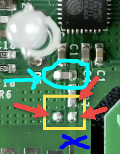
If I had to guess I’d say it’s an inductor that helps tuning the antenna (a.k.a. “antenna matching”) to the receiver (because it’s connected to GND) , but I’m not sure. Normally there would be two inductors and one capacitor (or vice versa). Or a resistor… Building antennas and antenna matching circuitry is a black art. If it was the dark ages you would probably be accused of witchcraft and burned alive if you had something to do with it! 
Aaaaaanyhow… In these low-end circuits with limited wattage, the performance is what it is. But as opposed to @wanek 's PCB, you can’t just flip the capacitor and add the connector. From what I can see on the picture, you have to physically cut (at the blue X) the path to disconnect the PCB antenna. Then you can solder a short coax cable to the pads and then to a connector. Looks like bottom left is GND.
Good luck!