Hello, to start with I’m a beginner home automation enthusiast.
- Everything connected to Local Network.
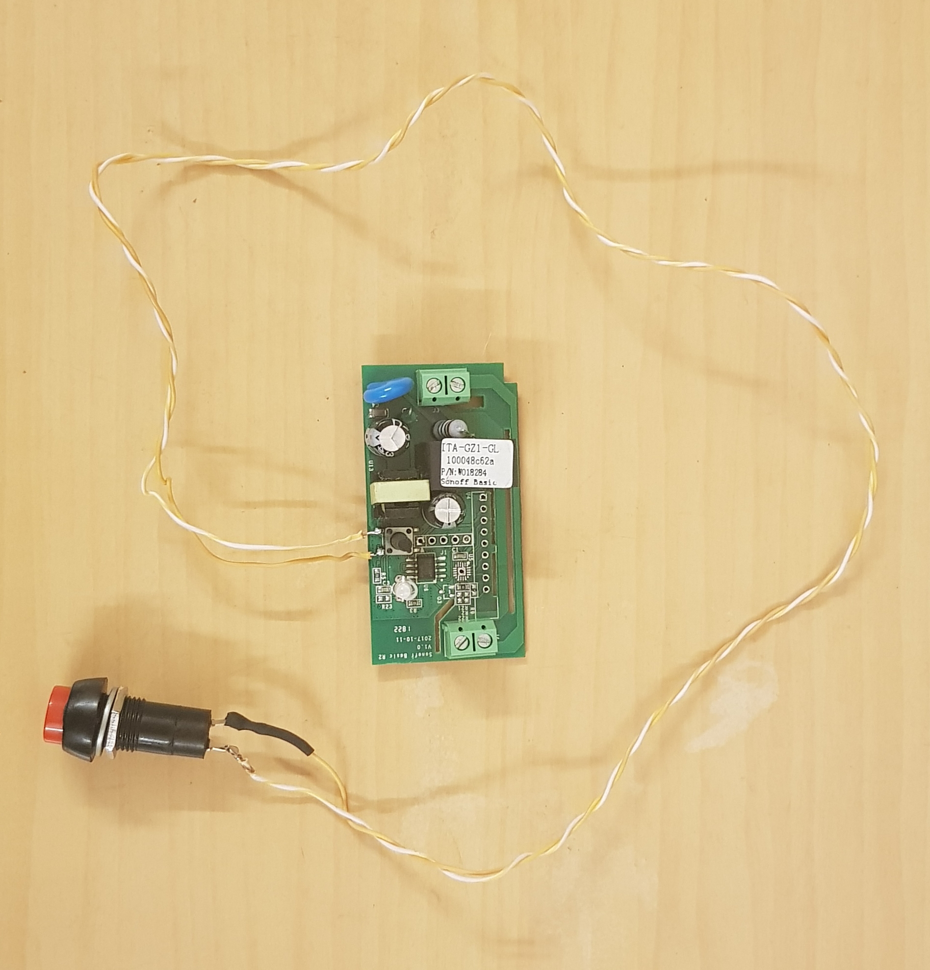
- Sonoff basic successfully flashed with sonoff boiler plate. (https://tzapu.com/sonoff-firmware-boilerplate-tutorial/)
- Switching from Blynk app works good on Samsung Galaxy S8+.
- When switching with physical button on sonoff, the on/off status on Blynk app doesn’t update while the relays on Sonoff turns on/off.
Code Link - https://github.com/tzapu/SonoffBoilerplate/blob/master/SonoffBoilerplate.ino
Library Used - https://github.com/blynkkk/blynk-library
- https://github.com/tzapu/WiFiManager
Can someone help me with how to update the Blynk’s on/off status when the physical button is pressed on Sonoff.
P.S. I’m planning to automate all my home switches & also use physical switches to turn them on/off & be able to check their live status from the app if someone switches them on/off by physical switch.
Are you just going to be relying on the small physical switches that are built-in to the Sonoff Basics, or are you thinking of adding some sort of external switch? (The answer to that question has an impact on the best hardware to choose and the GPIO pins that the switches will be connected to).
Have you changed the boilerplate code at all, and what values have you entered into Wi-Fi Manager when configuring the switch (don’t post your Blynk Auth code, I’m just interested in the rest).
Also, what country are you in?
Pete.
Thanks for the reply.
Is this a part or a complete code ?
Okay, the Sonoff Basic has a pin available that allows you to connect to GPIO14, so you could wire your external physical switches to GPIO14 and ground.
To get that working you’ll need to change this line of the code:
#define SONOFF_BUTTON 0
from 0 to 14.
Pete.
I’ve taken a look at the Sonoff Boilerplate code and I’m a bit confused about which virtual pins should be used.
The Blynk QR code here:
creates a project with the following widgets:
V0 - on (Button widget)
V1 - off (Button widget)
V2 - toggle (Button widget)
V5 - status (Value widget)
V6 - led (Led Widget)
however, the code says this is how the virtual pins should be configured:
/**********
 * VPIN % 5
 * 0 off
 * 1 on
 * 2 toggle
 * 3 value
 * 4 led
 ***********/
Maybe it’s something @tzapulica could take a look at?
As far as wiring your physical button across the existing button of the Sonoff, it’s not the way that I’d do it. You really want the existing physical button to be disabled if you’re burying the device in the wall, which is easy if you’re using a different GPIO for the external button, but would require a mechanical modification if not.
I asked about which country you’re in, because here in the UK, the majority of houses don’t have a Neutral wire available in the light switch. Only Line and switched Line are available at the light switch, so adding a Sonoff with a physical switch to the existing light switch plate isn’t an option without rewiring. (You’ve not explicitly said that this is for lighting, but I’ve made the assumption that lighting circuits will be involved in your whole house home automation project).
I’m not familiar with domestic wiring practices in India, but I’m assuming that you have both Line and Neutral available to you at the switch, or that you’re modifying the wiring to make that possible.
If that’s the case then you might be better going for something like the Sonoff T1 Wi-Fi Light Switch as this would give a much neater physical installation.
I noticed that you’ve not soldered a header into the Sonoff board to flash it, I assume that you’ve just pushed the header pins in there and held it in place while you flashed it. Once again, this inst how I’d do it as it can give unpredictable results.
Pete.
Thank you @PeteKnight. Well as I mentioned earlier I’m just a beginner so my basic knowledge or even understanding for backend development is zero.
Yes we usually have a neutral wire in India. And yes this project is for lighting & fans. 
Yes I pushed the header pins into place & flashed it.  (amateur)
@ldb I can’t understand anything. Can you please take the pain to explain how it works ?
Do the Blynk devs come up to help in this community because now things are getting complicated for me.
You can keep your Blynk widgets synchronized with the Blynk.virtualWrite statement. Just set the widget’s pin HIGH whenever the relay is turned on and LOW when it’s turned off.
for exeample:
Blynk.virtualWrite(V1, HIGH); // Force the Blynk button widget on virtual pin 1 to ON
Appreciate your help @chrome1000 ! I’ve no experience in coding but I still tried my hands on looking into it. Below I have pasted an extract of the coding where I made the changes to, I’ve no clue what to do where hence I hope this is the right place. The source code of this is : https://github.com/tzapu/SonoffBoilerplate/blob/master/SonoffBoilerplate.ino
BLYNK_WRITE_DEFAULT() {
int pin = request.pin;
int channel = pin / 5;
int action = pin % 5;
int a = param.asInt();
if (a != 0) {
switch(action) {
case 0:
turnOff(channel);
Blynk.virtualWrite(V1, LOW); // Force the Blynk button widget on virtual pin 1 to LOW
break;
case 1:
turnOn(channel);
Blynk.virtualWrite(V1, HIGH); // Force the Blynk button widget on virtual pin 1 to ON
break;
case 2:
toggle(channel);
break;
default:
Serial.print(“unknown action”);
Serial.print(action);
Serial.print(channel);
break;
}
}
}
Uh… not exactly. “V1” was just an example. You’d have to change that to the actual pin number of the Blynk widget you’d like to change. For example, if you’re using Alex’s boilerplate dashboard, and want to change the LED widget, you’d use
Blynk.virtualWwite(V5, 1023);
to turn it on, and
Blynk.virtualWrite(V5, 0);
to turn it off, because Alex’s LED widget is tied to virtual pin “V5”, and that widget’s brightness can be any value from 0 (off) to 1023 (fully on).