Some bridge questions

I’m moving to the next phase of my project: setting up the communication between the different devices. For simplicity sake I’ll limit it two 2 zones (there are in reality 7 in total). It turns out that this brings up a TON of questions, so apologies for the lengthy post…

SETUP:

Zone 1: Living Room

  • thermostat device (reads the temperature and shows the target temperature, has Up/Down button to change the target T)
  • relay device (turns on/off the pump and valve system)

Zone 2: Bed Room

  • thermostat device
  • relay device

CENTRAL Device, This is the processing unit that:

  • communicates with the blynk app (shows all states and temperatures)
  • receives current T from all thermostats
  • receives target T from all thermostats
  • sends ON/OFF state to all relays (which turns on/off pump, open/close valves)
  • sends ON/OFF to all thermostats (which show this state on screen)
  • sends target T update (when this is changed in the Blynk app) to all thermostats

QUESTIONS:
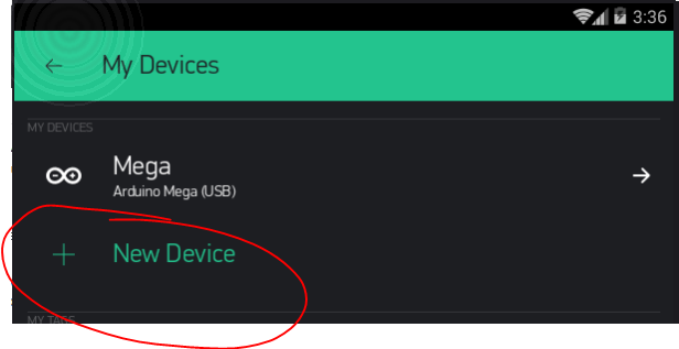
ANSWERED! 1. I gather from the documentation that EACH DEVICE requires its own authentication token. Is that right?
ANSWERED! 2. if so: how do I create these tokens? (do I need to create 12 projects for that, even though I’m only directly communicating with one: CENTRAL)?
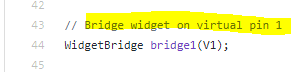
ANSWERED! 3. Can I change (from the documentation) this:

WidgetBridge bridge1(V1); //Initiating Bridge Widget on V1 of Device A

into this:

WidgetBridge bridge_livingroom(V1); //Initiating Bridge Widget on V1 of Device A

  1. if that is possible can I then keep using V1 for other zones as well so:
WidgetBridge bridge_livingroom(V1); 
WidgetBridge bridge_bedroom(V1); 
  1. When I push a value, how does the other side of the bridge ‘know’ that the value is pushed? I see this in the doc:
BLYNK_WRITE(V5){
    int pinData = param.asInt(); //pinData variable will store value that came via Bridge
}

but do I need to check (e.g. every second) whether V5 has changed? Or is there an event that is triggered? Or is BLYNK_WRITE() the event handler? E.g.:

BLYNK_WRITE(V5){ //V5 is heat indicator on the OLED screen of the thermostat
    int pinData = param.asInt(); //pinData variable will store value that came via Bridge
	heatOn = pinData; //heatOn is a Boolean
	updateOLED(); //this function updates the OLED screen indicating that the heat is on or off
}

ANSWERED! 6. Arduino-IDE when compiling it checks the board to which it compiles (Wemos D1) and allows me to use the pin numbers on the board instead of the gpio numbers, so D0, D1, D2, … A0. Lets say that the relay is connected to ‘D6’ can I update it directly and correctly with:

bridge_relay.digitalWrite(D6, HIGH);

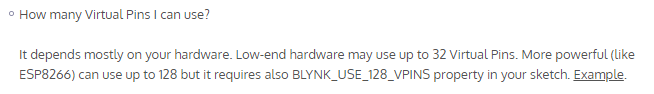
  1. to communicate everything with the app I need to communicate 5 values (target T, current T, heaton, maintenance and error) per zone. There are 7 zones, so 35 values to the app. Is that possible? Reason I ask is that the max virtual pin I see is: 31, so Im short 4. Any way around this?

Once more: thank you very much for looking at this!

Many questions… I will answer a few.

As you add devices within a project it will assign each an AUTH code.

image

Don’t see why not.

Don’t use those with Bridging… the Dpin references tend to be IDE board setting specific… use traditional GPIO pin numbering.

well that answers questions 1,2,3 and 6, leaving 4,5 and 7. Thank you for the swift reply!!

As long as each V1 is on a different device, why not :slight_smile: Try it.

Same way as it knows you touched a widget in the App… Blynk is constantly running in the background monitoring all it’s housekeeping needs.

Yes, by reading all the documentation… and I meen all of it, as there’s snippets of info here and there…

image

NOTE: most of these answers I discovered by simply experimenting and lots of reading :wink:

rtfm and experiment, yes I’m well aware. Currently I’ve read about 79 ‘manuals’ varying from lengthy fora pages, actual manuals, documentations, wiki pages, concerning Arduino, C, C++, Esp8266, Sonoff, Tasmota, LCD, OLED, RC filters, LM35, BME280, U8G2, Blynk, Adafruit and many many more. And yes at one point Ive read the blynk documentation from top to bottom (and I did read about the 128 VP but couldn’t recall where I read it).
As for experimenting, for the last 32 days I’ve been nearly every evening working on either Arduino or ESP or some electronical circuit, I still have to clean up the blood stains from the wall as it has become well-accustomed to my head :smiley:

I’ve also did research in Home-assistent, Cayenne, Node-red and openhab next to Blynk, to decide for which sytem I would go. I guess its obvious for which I went. The reason I did this is because I’ve been very active on a few other fora and know the enormous value of a big, friendly and supporting community. Of all these systems Blynk has the biggest and THAT is the main reason I decided to spend my foreseeable future here. As usual first as a leeching n00b and later (hopefully) as an experienced guide.

The questions I asked I could have indeed figured out by either rereading the docs again (although as you noticed, some questions literally concern the docs themselves) and by a lot of experimenting. However I would like to start this part of the (currently rather arduous journey) with some head-start…hence the questions. I have no doubt in my mind that I will be adding more bloodstains to the wall when I get deeper into the Blynk part of my project.

Anyway, once more (and I sincerely mean it!!: ) thank you for your support and swift replies. I hope I’ve given you enough motivation to convince you that I’m not quite as lazy as it might seem and that I had good reasons for asking them.

while working on this I encountered an additional question, in the docs this:

WidgetBridge bridge1(V1); //Initiating Bridge Widget on V1 of Device A

What is the function of “V1” in that line? Later in the code several values are send using this bridge over other virtual pins then 1, so does that mean that “V1” is completely arbitrary?

I ask this because in the end I will have 11 devices communicating with central and all using that exact line to initiate the bridge (then I will send updates over different pins per device of course)

Long seemingly defensive response for what was an innocent comment :stuck_out_tongue: I have been experimenting and reading about Blynk literally (and in the correct literal sense) every. single. day. for almost a year and a half… and I still need to rtfm :wink: And I also have a bloody dented wall… can’t seem to remembery why :thinking:

That is the vPin you assigned to the Widget in your App project of the sending device… it is clearer in the example referred to from the documents (at the end of the Bridge doc).

image


In your searching did you find this?

well it did give me the feeling that some explanation of my background, choices and intention needed to be clarified and I don’t mind doing that.

no I didn’t. I’ve read it a couple of times but I’m not sure im getting it. Perhaps some further explanation is in order:

Lets take the states heatOn and maintenanceOn, which are the two that are currently giving me a headache.

I have 3 devices: thermostat, relay and CENTRAL.

  1. The thermostat measures the current temp and checks it versus the target temp. If lower: heatOn is true, if higher heatOn is false

  2. The relay. If heatOn: relay is on, else its off. However its also checks if the state has changed in the past 12 hours. If not: maintenanceOn = true (for 5 minutes, then false again). During those 5 minutes heatOn != heatOn (its inverted, so the valve closes and opens during the 5 minutes, preventing it from getting stuck). The state is also send to the thermostat (via CENTRAL) for two reasons: 1. so its shows on the display and 2. preventing the thermostat from changing the heatOn state (as it will be ‘wrong’ during the cycle).

  3. CENTRAL: this one communicates with the blynk app and passes on maintenanceOn and heatOn between the thermostat and the relay. (while maintenanceOn=true: thermostat ‘freezes’).

Note thus that relay and thermostat do NOT communicate directly!

Now to communicate the states between the three devices I need the bridge, however I can’t wrap my head around which Vx I should use to do that. I’ve currently initiated all communication over V0 but the states are on V5 (heatOn) and V6 (maintenanceOn). So e.g. for central I have:

WidgetBridge bridge_thermostat(V0); 
WidgetBridge bridge_relay(V0); 

BLYNK_CONNECTED() {
    bridge_thermostat.setAuthToken("xxxx"); //auth of thermostat
    bridge_relay.setAuthToken("xxxx"); //auth of relay
}

// This function will be called every time Slider Widget
// in Blynk app writes values to the Virtual Pin 1

BLYNK_WRITE(V5){                                  //receive from either relay or thermostat
  heatOn_1 = param[0].asInt(); 
  String fromDevice = param[1].asString();
  Blynk.virtualWrite(V5, heatOn_1*200);             //TO BLYNK APP: displayed by a led with a luminosity ranging from 0 to 256
  if(fromDevice == "ESP_RELAY"){
    bridge_thermostat.virtualWrite(V5, heatOn_1); //TO THERMOSTAT: relay changed the state for maintenance
  } else {
    bridge_relay.virtualWrite(V5, heatOn_1);       //TO RELAY: Thermostat changed the state
  }
}

BLYNK_WRITE(V6){                                  //receive from relay
  maintenanceOn_1 = param.asInt();
  Blynk.virtualWrite(V6, maintenanceOn_1*200);//to BLYNK APP: turn on the led
  bridge_thermostat.virtualWrite(V6, maintenanceOn_1); //TO THERMOSTAT: relay changed the state for maintenance 
}

There’s more going on, but I’m trying to keep things simple for this question.

Now I haven’t tested it yet (it does compile though), but whether it works or not, what bugs me is:

WidgetBridge bridge_thermostat(V0); 
WidgetBridge bridge_relay(V0); 

I have no clue what its does and whether V0 is ‘right’.

EDIT: Reading your post again I get the feeling that I need to do this:

WidgetBridge bridge_thermostat(V5); 
WidgetBridge bridge_relay(V5); 
WidgetBridge bridge_thermostat(V6); 
WidgetBridge bridge_relay(V6); 

but if that is the case then I don’t get the documentation where they do:

WidgetBridge bridge1(V1); //Initiating Bridge Widget on V1 of Device A
and then

bridge1.virtualWrite(V1, "hello"); // you need to write code on Device B in order to receive this value. See below
bridge1.virtualWrite(V2, "value1", "value2", "value3");

In short: V2 is not initiated in the documentation, but it IS used.

For whatever reason you need a Widget in the sending devices project… that widget needs a vPin (possibly a different one for each individually named bridge)… However, from there any further bridge commands are using the receiving devices vPins that you want to control.

I recommend you start with a simple one-way bridge setup and test the :poop: out of it with every variation you can think of, before trying to make your full project functional with bridge.

My example was a bi-directional example… Take it, but load it on ONE device only and use a basic, non bridge sketch on the receiving end, with it’s own project, with Blynk functions buttons, LEDs whatever… then control them from the Bridge project.

I’ll get to it and see where it gets me, thnx.

well…I’m a bit flabbergasted…

I thought, well at least I can try to split everything up as it is and see where it gets me with the blynk bridge…it worked in one go :scream:
Granted: I had to fine tune some timers, what was communicated (and when) and the verbosity level of the serial output, but that was all minor stuf. The big jaw dropper is that this worked THE FIRST TIME, I don’t recall having that experience before with arduino.

I also got a bit of an epiphany when reading the docs for the nth time, specifically this line:

Bridge widget takes a virtual pin, and turns it into a channel to control another device.

It must have gone passed me all this time but now I understand that ALL communication is done through that one pin, whether you update virtual, digital or analogue pins, the updates go through that channel.

The only thing I still don’t get is why can you ALSO use that channel for other purposes, in the docs its used to initiate the communication channel AND its used to send the string “hello” (see example)
edit: ah no it doesn’t it updates V1 of the receiving device (@Gunner your words are beginning to make sense).

That leaves me wondering what happens if I were to initiate a channel on V0 and then either use a virtualwrite(V0,‘whatever’) either directly or from a remote device.

Anyway, my learning: I’ve reserved V0 for communication on ALL ESP’s and you apparently can even initiate multiple channels on the same pin. As I’ve done in CENTRAL:

WidgetBridge bridge_thermostat(V0); 
WidgetBridge bridge_relay(V0);

Yes, in the case of setting up the channel…

WidgetBridge bridge_thermostat(Vx); // vPin of transmitting device
bridge_thermostat.setAuthToken("OtherAuthToken"); // Token of the receiving device

The transmitting uses Vx out of it’s vPin selection for the channel

As to whether you can have multiple channels on a single vPin… I haven’t tested… it may only recognise the last one assigned :thinking:

But the server takes the transmitting command and sends that Vy value to the receiving device…

bridge_thermostat.virtualWrite(Vy, "hello");  // vPin of receiving device

I haven’t tried this, but I don’t see why you couldn’t use the same vPin # for both transmitting channel and receiving command as they are technically separate devices with their own AUTH code.

well I can tell you that you can. Everything works now!

only issue I just encountered is that if I connect them all to a USB adapter then the OLED screen of the thermometer get scrambled. Need to check whether I can either detect this or reset it regularly…

1 Like

UPDATE: and you shouldn’t…it turns out that using the same channel to communicate to two devices can work, but not reliably. This morning the Central–>Thermostat comm didn’t work, after changing the channel it did.

1 Like