[SOLVED] Virtual Pins - LEDs - WidgetLED - Blynk_Write ARRRUGGGHHHH

The frustrating thing is, you read other post (thousands) about the simple topic of using a virtual pin just to show the LED status of a digital or analog pin. Millions of examples !!! I can’t get one to work.

Do you load WidgetLED? What’s with the led1? Is that a generic reference meaning substitute the GPIO pin #? Do you load it within the Void Setup() or after? Are you supposed to put something after Void Loop() so it knows to keep your LED up to date? … I read that somewhere. If you load it in Void Setup() won’t it run once then go stale?

I read that someone was making a guide on Github for GetData, read that, didn’t cure my defective code.

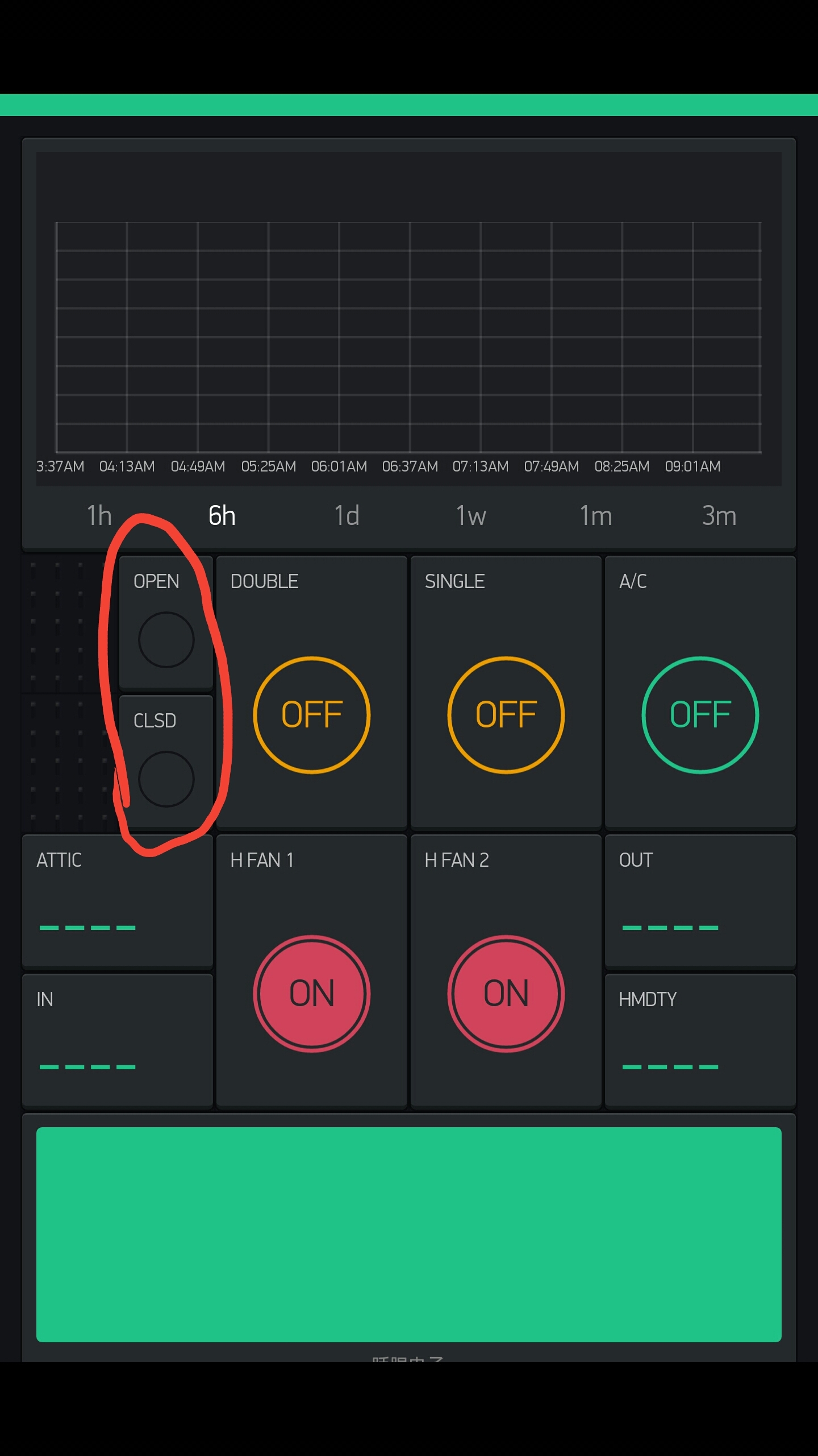
I’m a Dad, four kids, they all drive. I just want to know if the Garage Door is closed or open, when did it open or close, with a history log. Glance at my phone to see the “Clsd” or “Open” LEDs glow. :disappointed:

I know this is vhymanskyy’s most loathed topic YAGDO. If someone could peak into my super simple, cobbled together code and and throw me a bone I’d be grateful. I’ve got two Hall Sensors that work great. They light up an RBG (Red, Green) LED on my Breadboard (D2,D3) so I know what’s working on what’s not. The relay’s, simple as they are work great through Blynk. I’d rather key off the Hall GPIOs on the Analog side A3, A4 to free up the two digital pins once it’s mounted in the garage. I’ll take whatever works.

Thanks in advance !!!

// This #include statement was automatically added by the Particle IDE.
#include "blynk/blynk.h"
//
char auth[] = "b2784b3b3c594???????8752709100fd";

// Double Door Reed Swith CLOSED 
// ******************************
const int closedreedswitch = A4;
const int closedled = 2;
int hallstateclosed = 0;
//*******************************
//
// Double Door Reed Swith OPEN 
// ******************************
const int openreedswitch = A3;
const int openled = 3;
int hallstateopen = 0;

void setup () 
{
  Serial.begin(9600);
  Blynk.begin(auth);
    

 pinMode( 0 , OUTPUT); // Whole House Fan #1 Motor 4amp
 pinMode( 1 , OUTPUT); // Whole House Fan #2 Motor 4amp
 pinMode(closedreedswitch, INPUT);
 pinMode(closedled, OUTPUT);
// OPEN Reed Setup
 pinMode(openreedswitch, INPUT);
 pinMode(openled, OUTPUT);
 
  pinMode( 6 , OUTPUT); // Door One on Digital Pin D7
  pinMode( 4 , OUTPUT); // LED Indicator Light on Digital Pin D6
  pinMode( 7 , OUTPUT); // Door Two on Digital Pin D5
// The next two lines shutdown the relay so when the power bumps your doors don't pop open. 
  digitalWrite( 7 , LOW ); //Double Garage Door Switch
  digitalWrite( 6 , LOW ); //Single Garage Door Switch
  digitalWrite( 0 , HIGH ); //Whole House Fan #1
  digitalWrite( 1 , HIGH ); //Whole House Fan #2
  delay( 1000 );
  digitalWrite( 4 , LOW ); // This is the LED indicating the program has started.
  delay( 450 );
  digitalWrite( 4 , HIGH );
  delay( 250 );
  digitalWrite( 4 , LOW );
  delay( 250 );
  digitalWrite( 4 , HIGH );
  delay( 250 );
  digitalWrite( 4 , LOW );
  delay( 250 );
  digitalWrite( 4 , HIGH );
  delay( 250 );
  digitalWrite( 4 , LOW );
  delay( 250 );
  digitalWrite( 4 , HIGH );
  delay( 250 );
  digitalWrite( 4 , LOW );
  delay ( 250 );
  digitalWrite( 4 , HIGH);
  delay ( 250 );
  digitalWrite( 4 , LOW); 
}
// ---------[ Widget Button using  virtual pin # 0 ]--------------------

BLYNK_WRITE(V0) 
{
  if (param.asInt() == 0) 
  {   
   digitalWrite(2, LOW); //GPIO2
  } 
  else 
  {
  digitalWrite(2, HIGH); // GPIO2
  }
}

void loop() 
{
  Blynk.run();

// CLOSED Reed Part of Loop    
 hallstateclosed = digitalRead(closedreedswitch);

  if (hallstateclosed == LOW){
    digitalWrite(closedled, HIGH);
      }
  else{
    digitalWrite(closedled, LOW);

/// OPEN Reed Part of Loop

 hallstateopen = digitalRead(openreedswitch); 

  if (hallstateopen == LOW){
    digitalWrite(openled, HIGH);
      }
  else{
    digitalWrite(openled, LOW);
    
   }}}
1 Like

@Lane0138 just had a quick look at your sketch. You might want to look up ‘Arduino for loops’ for the initial LED flash when the system starts.

For the problem with the LED’s not responding to a virtual button try:

BLYNK_WRITE(V0) 
{
  int LEDonoff = param.asInt() ;
  if (Ledonoff == 0) 
  {   
   digitalWrite(2, LOW); //GPIO2
  } 
  else 
  {
  digitalWrite(2, HIGH); // GPIO2
  }
}
1 Like

Costas,

Thanks for the tips and the quick reply. I’m working on the loop too, but in the meantime I dropped your code in but it wouldn’t compile? Where is the proper place to place these lines, the Setup, Loop or after Loop?

It said in the error msg: “error: ‘Ledonoff’ was not declared in this scope”. On the first “if” statement.

// This #include statement was automatically added by the Particle IDE.
#include "blynk/blynk.h"
//
char auth[] = "b2784b3b3c5945e????4f8752709100fd";

// Double Door Reed Swith CLOSED 
// ******************************
const int closedreedswitch = A4;
const int closedled = 2;
int hallstateclosed = 0;
//*******************************
//
// Double Door Reed Swith OPEN 
// ******************************
const int openreedswitch = A3;
const int openled = 3;
int hallstateopen = 0;

void setup () 
{
  Serial.begin(9600);
  Blynk.begin(auth);
    

 pinMode( 0 , OUTPUT); // Whole House Fan #1 Motor 4amp
 pinMode( 1 , OUTPUT); // Whole House Fan #2 Motor 4amp
 pinMode(closedreedswitch, INPUT);
 pinMode(closedled, OUTPUT);
// OPEN Reed Setup
 pinMode(openreedswitch, INPUT);
 pinMode(openled, OUTPUT);
 
  pinMode( 6 , OUTPUT); // Door One on Digital Pin D7
  pinMode( 4 , OUTPUT); // LED Indicator Light on Digital Pin D6
  pinMode( 7 , OUTPUT); // Door Two on Digital Pin D5
// The next two lines shutdown the relay so when the power bumps your doors don't pop open. 
  digitalWrite( 7 , LOW ); //Double Garage Door Switch
  digitalWrite( 6 , LOW ); //Single Garage Door Switch
  digitalWrite( 0 , HIGH ); //Whole House Fan #1
  digitalWrite( 1 , HIGH ); //Whole House Fan #2
  delay( 1000 );
  digitalWrite( 4 , LOW ); // This is the LED indicating the program has started.
  delay( 450 );
  digitalWrite( 4 , HIGH );
  delay( 250 );
  digitalWrite( 4 , LOW );
  delay( 250 );
  digitalWrite( 4 , HIGH );
  delay( 250 );
  digitalWrite( 4 , LOW );
  delay( 250 );
  digitalWrite( 4 , HIGH );
  delay( 250 );
  digitalWrite( 4 , LOW );
  delay( 250 );
  digitalWrite( 4 , HIGH );
  delay( 250 );
  digitalWrite( 4 , LOW );
  delay ( 250 );
  digitalWrite( 4 , HIGH);
  delay ( 250 );
  digitalWrite( 4 , LOW); 
}
// ---------[ Widget Button using  virtual pin # 0 ]--------------------

BLYNK_WRITE(V0) 
{
  int LEDonoff = param.asInt() ;
  if (Ledonoff == 0) 
  {   
   digitalWrite(2, LOW); //GPIO2
  } 
  else 
  {
  digitalWrite(2, HIGH); // GPIO2
  }
}

void loop() 
{
  Blynk.run();

// CLOSED Reed Part of Loop    
 hallstateclosed = digitalRead(closedreedswitch);

  if (hallstateclosed == LOW){
    digitalWrite(closedled, HIGH);
      }
  else{
    digitalWrite(closedled, LOW);

/// OPEN Reed Part of Loop

 hallstateopen = digitalRead(openreedswitch); 

  if (hallstateopen == LOW){
    digitalWrite(openled, HIGH);
      }
  else{
    digitalWrite(openled, LOW);
    
   }}}

Costas,

Even I should have caught this:

int LEDonoff = param.asInt() ;
if (Ledonoff == 0)

The syntax wasn’t consistent on the LEDonoff. One was CAPS “LEDonoff” the next ref line was missing the CAPS “Ledonoff”.

I’ll give it another try. Thanks again.

*** 10 mins later: ***

The code compiled but V0 LED on the Blynk App wouldn’t light up. I have an LED (I mentioned this) on my Breadboard so I can see what the Hall Sensors and the Photon are doing. Everytime I pass the magnet past either of the two Hall Sensors the LED on the BB lights up (D2&D3)… Green and Blue. I also tested D2 with my Voltmeter when I pass the magnet in front of the Hall Sensor and I get 3Vdc. I’m stuck on why the Blynk App isn’t indicating the same thing.

Any additional advice would be great.

Thanks - Lane0138

Sorry I thought it was the LED’s on the breadboard that you were wanting to light up.

The BLYNK_WRITE(V0) extracts are functions in their own right so they sit outside the loop and Blynk.run() in the loop calls them as and when required.

If you want to light an LED in your app then you need a virtual Write. So if app green LED is on V5 and red LED is on V6 the pseudo code is:

// CLOSED Reed Part of Loop    
 hallstateclosed = digitalRead(closedreedswitch);

  if (hallstateclosed == LOW){
    Blynk.virtialWriteWrite(V5, HIGH);
      }
  else{
    Blynk.virtualWrite(V5, LOW);
  }

/// OPEN Reed Part of Loop

 hallstateopen = digitalRead(openreedswitch); 

  if (hallstateopen == LOW){
    Blynk.virtialWrite(V6, HIGH);
      }
  else{
    Blynk.virtialWrite(V6, LOW);
  }
1 Like

This is great, i was also stuck on this problem with virtual pins and where in the code to put things
as i am sure a lot of other people are!
Think some more basic guides are required.
Thanks Costas!

@Stubby we have docs regarding virtual pins. Did you read it?

Looks like i’ve got some more reading to do thanks for that, i do however find it a lot easier to work out
whats going on from a block of code being used, as above. Thanks for your help and “Blynk” im so excited
with the possibilities!

Stubby,

I’m with you… “more basic guides” would be nice.

Dmitriy, love the product and it’s endless potential, but if something as simple as lighting an indicator LED on the Blynk App get’s this many people stuck, maybe there does need to be more guides. I’ve seen most all of your post on this topic and I’ve notice time and time again your refer to the guides but they just aren’t that clear. I will say that with a caveat, if your target user has a four year Programming Degree and five more years minimum coding experience, then I’m afraid I’ll have to bow out. If the target is the weekend coder, project maker I’d love to participate and build the hundreds of things for my house rolling around in my head.

Pavel said “there will be Members and Business”, 10k or 1mill subscribers only time will tell. But if your goal is the “masses” project members, there has got to be better guides and examples if members are expected to pay a monthly fee. WE have to get the projects to work or what’s the point?

I still can’t get the LEDs in the app to light…

2 Likes

@Lane0138 let me see your sketch as you have it now together with the dashboard details and I’ll see what I can do.

EDIT:

I notice in my last sketch extract that I can’t spell virtual. Revised sketch extract below.

// CLOSED Reed Part of Loop
hallstateclosed = digitalRead(closedreedswitch);

  if (hallstateclosed == LOW){
    Blynk.virtualWriteWrite(V5, HIGH);
      }
  else{
    Blynk.virtualWrite(V5, LOW);
  }

/// OPEN Reed Part of Loop

 hallstateopen = digitalRead(openreedswitch); 

  if (hallstateopen == LOW){
    Blynk.virtualWrite(V6, HIGH);
      }
  else{
    Blynk.virtualWrite(V6, LOW);
  }

In our actual sketches we don’t have HIGH and LOW for the virtual LED’s. We use 255 and 0 as you can set a brightness for the LED’s between 0 and 255 so it might be better forgetting HIGH and LOW as HIGH might be interpreted as 1 which will hardly register in the dashboard. So something like this:

// CLOSED Reed Part of Loop    
 hallstateclosed = digitalRead(closedreedswitch);

  if (hallstateclosed == LOW){
    Blynk.virtualWriteWrite(V5, 255);
      }
  else{
    Blynk.virtualWrite(V5, 0);
  }

/// OPEN Reed Part of Loop

 hallstateopen = digitalRead(openreedswitch); 

  if (hallstateopen == LOW){
    Blynk.virtualWrite(V6, 255);
      }
  else{
    Blynk.virtualWrite(V6, 0);
  }

Costas,

Thanks for taking a look at it. It’s like other section of the code, if you can get it to work once it all makes sense. I’ve tried at least 10 different variations of this from the many guides listed. Thanks for jumping in…

P.S. I’m working on the repeat blink on the side.

// This #include statement was automatically added by the Particle IDE.
#include "blynk/blynk.h"
//
char auth[] = "b2784b3b3c5945e2894f8752709100fd";

// Double Door Reed Swith CLOSED 
// ******************************
const int closedreedswitch = A4;
const int closedled = 2;
int hallstateclosed = 0;
//*******************************
//
// Double Door Reed Swith OPEN 
// ******************************
const int openreedswitch = A3;
const int openled = 3;
int hallstateopen = 0;


hallstateclosed = digitalRead(closedreedswitch); ///this causes an error...

  if (hallstateclosed == LOW){
    Blynk.virtualWrite(V0, HIGH);
      }
  else{
    Blynk.virtualWrite(V0, LOW);
  }


void setup () 
{
  Serial.begin(9600);
  Blynk.begin(auth);
    

 pinMode( 0 , OUTPUT); // Whole House Fan #1 Motor 4amp
 pinMode( 1 , OUTPUT); // Whole House Fan #2 Motor 4amp
 pinMode(closedreedswitch, INPUT);
 pinMode(closedled, OUTPUT);
// OPEN Reed Setup
 pinMode(openreedswitch, INPUT);
 pinMode(openled, OUTPUT);
 
  pinMode( 6 , OUTPUT); // Door One on Digital Pin D7
  pinMode( 4 , OUTPUT); // LED Indicator Light on Digital Pin D6
  pinMode( 7 , OUTPUT); // Door Two on Digital Pin D5
// The next two lines shutdown the relay so when the power bumps your doors don't pop open. 
  digitalWrite( 7 , LOW ); //Double Garage Door Switch
  digitalWrite( 6 , LOW ); //Single Garage Door Switch
  digitalWrite( 0 , HIGH ); //Whole House Fan #1
  digitalWrite( 1 , HIGH ); //Whole House Fan #2
  delay( 1000 );
  digitalWrite( 4 , LOW ); // This is the LED indicating the program has started.
  delay( 450 );
  digitalWrite( 4 , HIGH );
  delay( 250 );
  digitalWrite( 4 , LOW );
  delay( 250 );
  digitalWrite( 4 , HIGH );
  delay( 250 );
  digitalWrite( 4 , LOW );
  delay( 250 );
  digitalWrite( 4 , HIGH );
  delay( 250 );
  digitalWrite( 4 , LOW );
  delay( 250 );
  digitalWrite( 4 , HIGH );
  delay( 250 );
  digitalWrite( 4 , LOW );
  delay ( 250 );
  digitalWrite( 4 , HIGH);
  delay ( 250 );
  digitalWrite( 4 , LOW); 
}
// ---------[ Widget Button using  virtual pin # 0 ]--------------------


void loop() 
{
  Blynk.run();

// CLOSED Reed Part of Loop    
 hallstateclosed = digitalRead(closedreedswitch);

  if (hallstateclosed == LOW){
    digitalWrite(closedled, HIGH);
      }
  else{
    digitalWrite(closedled, LOW);
    
 
/// OPEN Reed Part of Loop

 hallstateopen = digitalRead(openreedswitch); 

  if (hallstateopen == LOW){
    digitalWrite(openled, HIGH);
      }
  else{
    digitalWrite(openled, LOW);
    
   }}}

@Lane0138 sure there always could be better. However we are very limited in resources so we have to put priorities among hundreds of tasks we have :slightly_smiling:. You will be surprised but even docs I’'m pointing to appeared only few months ago. And of course you are very welcome to make any proposals and even contribute.

@Lane0138 change the HIGH and LOW to 255 and 0 as per my last post.

Costas,

I’ll give that a try. Where do I insert this. You said not to put it in the loop, I get that, Blynk disconnects your app if you do. I put it above after the Setup but I get errors on the first line. Do you put it after a Void State() or something?

I inserted it in this fashion:

//*******************************
//
// Double Door Reed Swith OPEN 
// ******************************
const int openreedswitch = A3;
const int openled = 3;
int hallstateopen = 0;


 hallstateclosed = digitalRead(closedreedswitch);

  if (hallstateclosed == LOW){
    Blynk.virtualWrite(V0, 255);
      }
  else{
    Blynk.virtualWrite(V0, 0);
  }

/// OPEN Reed Part of Loop

 hallstateopen = digitalRead(openreedswitch); 

  if (hallstateopen == LOW){
    Blynk.virtualWrite(V1, 255);
      }
  else{
    Blynk.virtualWrite(V1, 0);
  }

void setup () 
{
  Serial.begin(9600);
  Blynk.begin(auth);

I get the error:

error: ‘hallstateclosed’ does not name a type
const int openreedswitch = A3;

@Lane0138 it needs to be in a Blynk function relating to the physical pins for the reedswitches. So if the reedswitch was on digital pin 1 and the LED is virtual pin 1 it would be as shown below and located anywhere outside setup and loop:

BLYNK_WRITE(1) { 
  int hallstateclosed = param.asInt();
  if (hallstateclosed == 0) { 
   virtualWrite(V1, 255);
  }
 else{
   virtualWrite(V1, 0);
 }
}

Dmitriy,

In your code, in the example your referenced, I don’t understand why there appears to be a missing Virtual pin reference, like V3 or something.
Does …Blynk.virtualWrite (ledPin2, led2value); = Blynk.virtualWrite (V3, led2value); ??

(Instructables :How to use virtual pins?)

In a comment made by Costas he said we should avoid using HIGH and use 255. Are these interchangeable terms and conditions?

int prev = HIGH;
void loop()
{
  Blynk.run();
  int led2value = digitalRead (ledPin2); 
  if (led2value != prev){  
    Blynk.virtualWrite (ledPin2,led2value);}  
              
      prev = led2value;
    
}

Costas,

I’ll give it a try in a bit. Got an appt. Thanks for your help.

I’ll let you know how it goes. I appreciate all your effort to this small cause.

Lane

Yes. instead of ledPin2 you can use any virtual (to be specific - those one you select on UI in Blynk app.).

I would recommend to use WidgetLED.

WidgetLED led(V3);

int prev = HIGH;

void loop() {
  Blynk.run();

  int led2value = digitalRead (ledPin2); 
  if (led2value != prev) {  
     if (led2Value == HIGH) {
         led.on();
     } else { 
         led.off();
     }
         
     prev = led2value;
  }  
}

@Lane0138 when you do get back to this take a look at the following example https://github.com/blynkkk/blynk-library/blob/master/examples/Widgets/LED/LED.ino#L31

If you declare the LED’s e.g. WidgetLED led1(V1); then you can use led1.getValue() and led1.setValue() to read and write the intensity of the virtual LED between 0 and 255. We don’t declare our LED’s so I think HIGH and 255 are interchangeable.

To test the basic on / off of virtual LED’s you might want to just add a button in the app set to switch mode (rather than push mode) against a digital pin e.g. 1 and use my last extract.

BLYNK_WRITE(1) { 
  int hallstateclosed = param.asInt();
  if (hallstateclosed == 0) { 
   virtualWrite(V1, 255);
  }
 else{
   virtualWrite(V1, 0);
 }
}

You can then toggle the LED on and off with the app and then progress to the reedswitches doing it for you.