I saw some topics about this before. I got the code right, but can’t seem to figure out the wiring ?
I am using D8 on a wemos D1.
If anyone can help me with this noob question thanks
but what exactly would you like to know?
How to wire the button
https://www.arduino.cc/en/Tutorial/Button
this is the simple part. but you have to take care that on wemos a lots of pins have built in pullup or pulldown resistors. and if you 're not aware of this, maybe you will end up trying to pull down a pin with your external resistor which is already pulled up by built in resistor 
for this, study the d1 board at wemos.cc
also, you should implement some sw or hw debouncing, to have the expected results.
1 Like
@Dema323 You young punks, always asking for handouts ;)… Don’t make me slap a RE-SEAR-CH label on you ![]()
Actually I am awaiting some Wemos dev boards… so I will need to start unlearning Arduino and relearning ESP myself… and asking questions… poor me ![]()
Based on this
https://wiki.wemos.cc/products:d1:d1
Pin D8 has a built in 10k pulldown, so you would probably be best to pull-up your button to trigger.
1 Like
Damn i almost went unoticed and got away with it 
1 Like
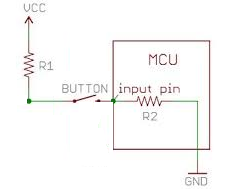
I don’t understand why you’d put R1 between VCC and the switch.
When you press the switch you want the ‘input pin’ to be pulled high (to VCC level, which is 3.3v). Putting a resistor between VCC and the switch simply lowers the voltage being applied to the input pin, which is unnecessary in my opinion.
Pete.
It isn’t absolutely necessary, but generally good practice to have current limiting resistors for pin protection.
I thought it was generally accepted that current-limiting resistors aren’t used on MCUs because of the high input impedance if the digital pins.
Pete.
Yey im not the only one who learns stuff from this topic 
you’re right, i also never used current limiting resistor for this.
but i think @Gunner has thought about some very “worst case scenario”: if some enemy or terrorist - say - in secret reconfigures the pin function in the code to: pinmode output and digitalwrite low.
in this case, pressing the button would instantly fry the respective pin
You know that you don’t have to follow my internet found clipart example to the Hilt ![]()
I meanwhile will continue to use resistors, or not, depending on my circumstances… dem pesky terrorists always mixing up my 5v and 3.3 v PSUs ![]()
2 Likes
but against this, the resistors won’t protect the mcu ![]()
I don’t know all the theory, but it probably would help protect for a short while; As the higher voltage can carry greater current, the current limiting should keep things from instantly frying… and I am not the only one thinking this ![]()
https://www.digikey.ca/en/articles/techzone/2012/apr/protecting-inputs-in-digital-electronics
http://www.kevinmfodor.com/home/My-Blog/microcontrollerinputprotectiontechniques
And so on…
Personally, I will keep practicing and preaching this method, what is a few resistors compared to replacing MCUs ![]() (Ironically, I need to follow my own advice when powering LEDs from MCUs… as I usually test them without resistors… However, the risk is higher on the single LED’s end then the MCU’s).
(Ironically, I need to follow my own advice when powering LEDs from MCUs… as I usually test them without resistors… However, the risk is higher on the single LED’s end then the MCU’s).
interesting article. however, afaik the series resistor will not protect from over voltage, only for over current.
at least the atmel mcus are quite sensitive to over voltage. anything above 0.5v over the vcc will possibly fry the controller: if you run the mcu at 5.0v for example, any voltage >5.5v can potentially kill it. (once, by mistake, i destroyed an atmega328: it was supplied with 3.3v but the programmer spi ttl was set to 5.0v…)
if i remember correctly, the esp is much more robust from this pow, they have some kind of protection circuit implemented on the io pins.
They are related, so some limited protection can occur… (hopefully long enough to realise I used the wrong Vin ;P… so far I have yet to kill an MCU that way, but not for lack of trying ![]() ).
).
And while not nearly as reliable, compared to a voltage divider, etc, some use a single resistor as a ghetto voltage level protection when passing 5v TX to 3.3v RX pin… becasue it sorta works… at least for awhile.
Closing old topic after two years