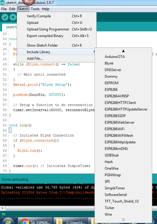
I’m using ESP8266 development board. It came with NodeMCU flashed. Using latest version Arduino IDE and necessary ESP8266 and Blynk libraries installed.
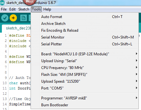
In IDE I selected NodeMCU as the board for port COM. Through IDE I’m able to flash my program. program runs and connects to Blynk cloud fine and I’m able to use widgets. I have customized functions working fine.
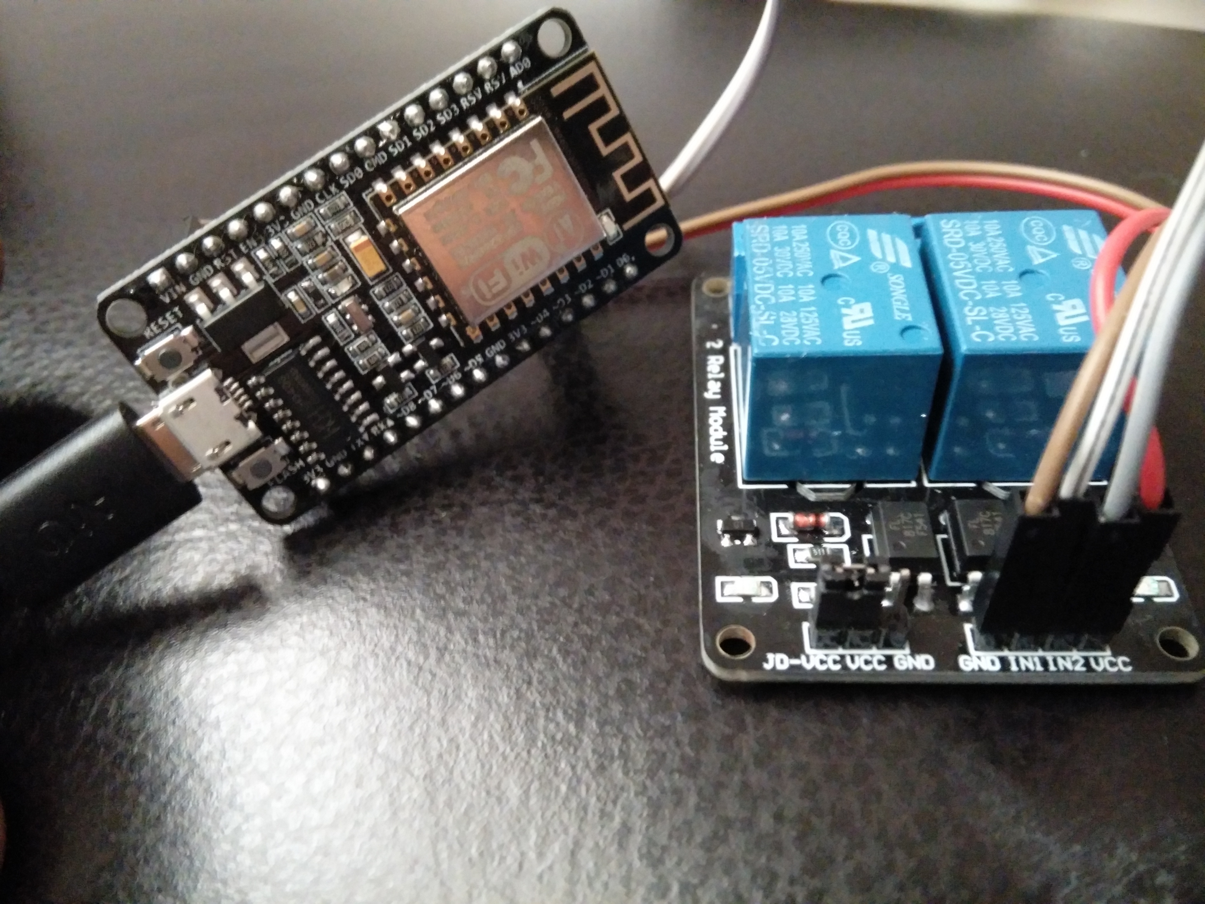
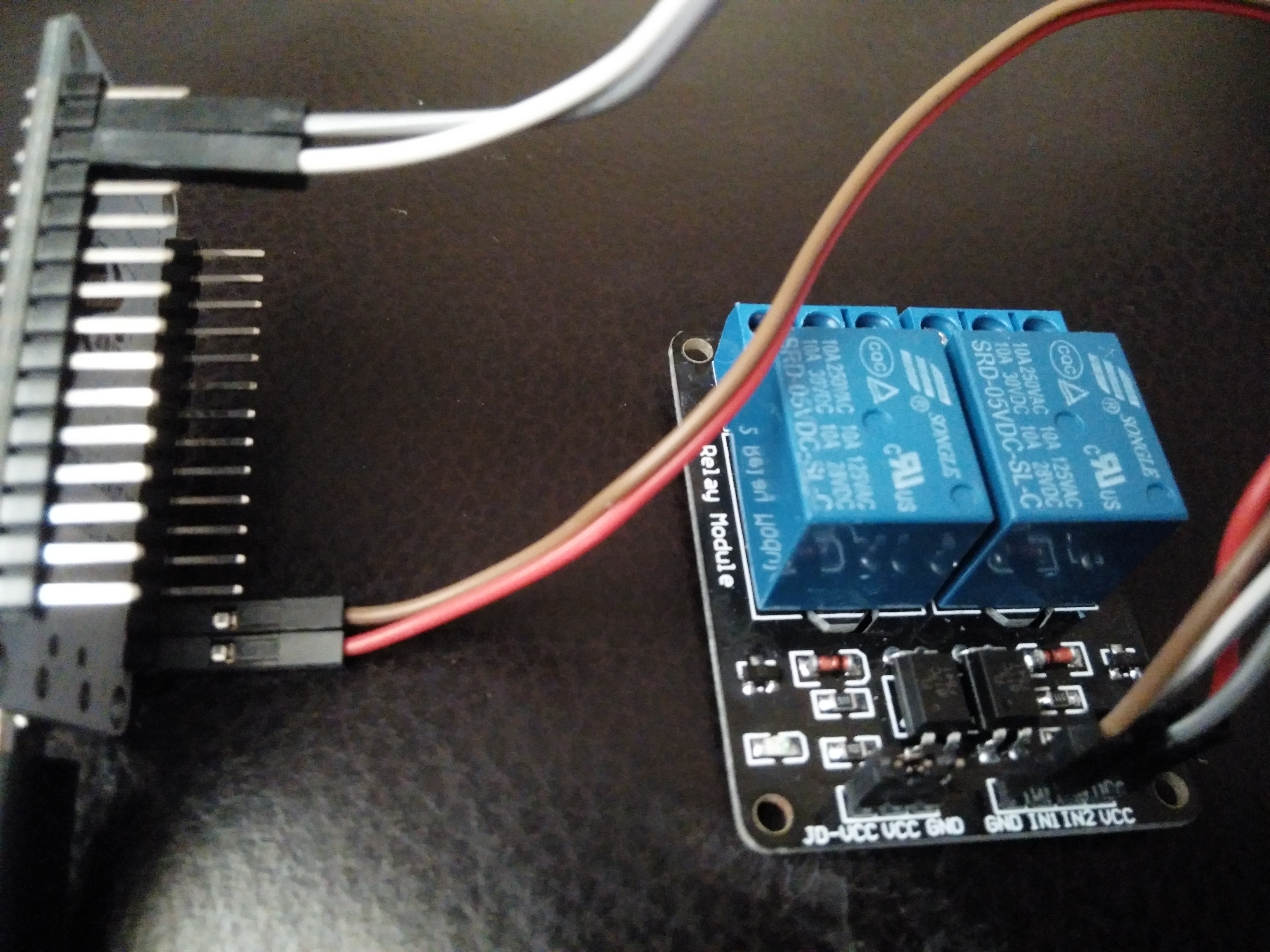
I connected 2 channel relay and connected 5v power, ground wires correctly. Also connected D1 and D2 to relay IN1 and IN2.
Through NodeMCU I can control D1 and D2 and the relay clicks.
– set pin index 1 to GPIO mode, and set the pin to high.
pin=1
gpio.mode(pin, gpio.OUTPUT)
gpio.write(pin, gpio.HIGH)
gpio.write(pin, gpio.LOW)
gpio.write(pin, gpio.IN)
But following code written in Ardunio flashed to the board is not working with relay.
What kind of relay do you use? Maybe there is a jumper missing to select if the relay should react on low or high input?
And why do you set the pin to input after your instructions?
#define BLYNK_PRINT Serial    // Comment this out to disable prints and save space
#include <BlynkSimpleEsp8266.h>
#include <SimpleTimer.h>

#define WIFI_SSID "iHome"
#define WPA_PASSWORD "xxx"


// Auth Token for the Blynk App.
char auth[] = "xxx";
int DoorPin = 1;

//Time Object
SimpleTimer timer;

//Set Door Pin to HIGH/LOW
BLYNK_WRITE(V1)
{
  pinMode(DoorPin, OUTPUT);
  if(digitalRead(DoorPin) == LOW)
  {
    digitalWrite(DoorPin, HIGH);
    Serial.print("Pin set to HIGH");
  }
  else
  {
    digitalWrite(DoorPin, LOW);
    Serial.print("Pin set to LOW");
  }
  pinMode(DoorPin, INPUT);
}


//Try reconnecting to Blynk
void reconnectBlynk()
{
  if (!Blynk.connected())
  {
    if (Blynk.connect())
    {
      Serial.print("Blynk Reconnected");
    }
    else
    {
      Serial.print("Blynk Not reconnected");
    }
  }
}

void setup()
{
  Serial.begin(9600); // See the connection status in Serial Monitor
  Blynk.begin(auth, WIFI_SSID, WPA_PASSWORD); //insert here your SSID and password

  while (Blynk.connect() == false)
  {
    // Wait until connected
  }
  Serial.print("Blynk Setup");

  // Setup a function to do reconnection attempts once a minute
  timer.setInterval(60000, reconnectBlynk);
}

void loop()
{
  // Initiates Blynk Connection
  if (Blynk.connected())
  {
    Blynk.run();
  }

  timer.run(); // Initiates SimpleTimer
}
I think I know these relays, I have a couple of those and they switch on with LOW and off with a HIGH signal. Have you tried “manually” controlling the relay’s by just putting a wire on them with +5v or GND? So, bypassing your programming and logic to see if the relays physically work?
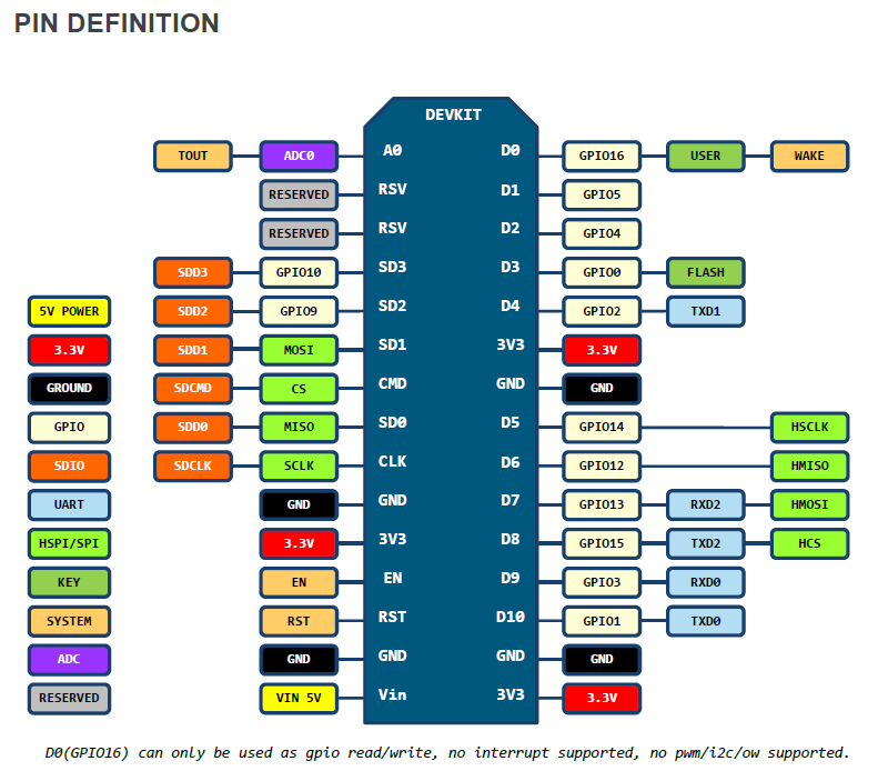
I learned the hard way that pins numbers are differently addressed between NodeMCU and Arduino. In NodeMCU D1 and D2 can be referred as pin 1 and 2 but in Arduino we have to use actual GPIO numbers. For D1 GPIO address is 5 and for D2 GPIO 4…