Hello everyone,
Having a problem with relays and cannot get the point.
I have 2 Arduino MKR1010 WiFi, latest Blynk library version, code with Arduino IDE on Mac OS.
On the first, I have a single relay connected just with Signal and GND pins, no VCC and works perfectly on Button Widget (Push/Switch) set to Digital Pin with no code, just declared the pin to be OUTPUT in the void setup.
On the second I have a 4 channel relay shield fully connected (VCC to VCC, GND to GND and Signal1-4 to D1-D4, won’t work without VCC pin). 4 widgets directly connected to D1-D4
and I had exactly the same behavior, but if I switch 0-1 with 1-0 in the Widget the relay starts always HIGH but goes to LOW in a few seconds and then works correctly.
this happen after any reboot of the Arduino and it is of course not acceptable because those relays will switch on and off other Arduinos on demand. The only solution I could think is to switch NC to NO on the other side of relays, but this would mean keeping HIGH the relays for most of the time and I am on battery power… I don’t know what is the exact power consumption, but I think it’s not a good idea anyway.
I tried 3 different 4 channel relays modules and they all work the same.
Can you help me solve this? I’m at your disposal for further tests.
That’s a very bad idea, you will (sooner or later) like the digital pin on your Arduino, and (as you’ve discovered) the relay won’t work as it’s designed to.
Most relay boards are designed to be Active LOW, so you power them up and then the relays are activated by connecting the signal pins to GND.
This means that it’s a good idea to add a pinMode(OUTPUT) followed by a digitalWrite(HIGH) to ensure that the relays are off (the coils are not energised) initially.
When powering your relays, it’s a good idea to ensure that the VCC connection does not go via the circuitry on the Arduino, as the relays may draw more current than the onboard voltage regulator can provide. If your relays require 5v and you are powering your Arduino via USB then you will probably get away with tapping in to that USB power for a 4 relay board, provided you have a decent (2 amp) USB power supply.
If you go to larger relay boards (or start having reboot issues) then I’d suggest using a separate power supply for the relays.
Actually this is the only one working correctly. It stays LOW all the time unless I push the in-app button or the loop launches a digitalWrite, which is exactly the behavior I want.
I know it’s not good to power it by the signal pin, in fact I arranged a terminal for power inlet. I didn’t connect it yet because I’m still completing it. Anyway the pin has to power the relay for 1 second twice a day, if the sky is clear, so I may consider leaving it this way.
Both Arduino and the 4-relays board are powered via a LM2596 3A step-down buck converter 12V → 3,3V. I tried also to power via the Arduino on first try: it work exactly the same, but on the sofa I was more comfortable
Already tried to setup with the digitalWrite(HIGH), but nothing changed in the behavior: It start HIGH.
When I say “relay HIGH” I mean coil energised (the LED is ON, the Normally Open inlet has power, the Normally Closed has not)
Actually, I don’t think it is working as designed, for the reasons I outlined earlier, it’s just giving the results you are looking for because you are only powering the relay when you want it to be activated.
This is poor use of terminology. I think you mean that the relay remains de-energised unless the button is pressed.
You need to determine if your relay boards are expecting a LOW or a HIGH signal on their input pins to energise the relay coil. Do this by disconnecting them from the MCU and powering then via the VCC and GND pins, then connecting one of the signal pins to GND and VCC in turn. If connecting to the GND pin makes the LED light and the relay click on then the relay is active LOW. If this happens when the signal pin is connected to VCC then the relays are active HIGH.
Do this test and report back on your findings. I’d recommend doing it for both your single and double relay boards.
Okay, so you need to write your code for the 4-way relay in a way which sets the pins HIGH in void setup and LOW in your code that activates the relays.
If you’re doing this by direct (digital) pin manipulation in the app then you’ll need to change the button widgets to 1/0 instead of the default 0/1.
If you’re using virtual pins and BLYNK_WRITE(vPin) callbacks then you could also change the widget buttons in this way, but my preference is to keep them as standard and write the code in the BLYNK_WRITE accordingly.
I would also recommend changing the way your single relay is wired, as you do risk killing the board eventually.
Ok now it’s working.
I was very sure I already did the digitalWrite(HIGH); try, but it is evident I didn’t.
Now there is another problem: if I energise relays (one or more) via switch button, after few seconds (can be 3s, or 30s random) they automatically de-energise and become unresponsive for a while. The switch button remains ON and I have to Switch OFF manually.
Is it due to insufficient powering?
They are 5VDC relays and I tried powering them at both 3,3V and 5V without differences.
There is no code after setup because I’m now trying them directly on Digital Pin
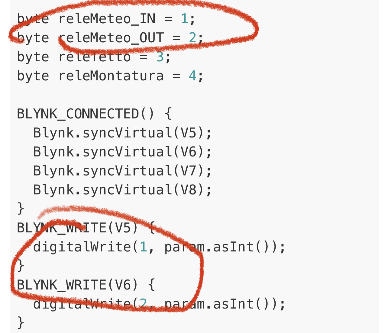
Ok, I changed the code to virtual pins use.
The problem remains, but I had no problem when I was using them with LOW starting. They stayed on for an hour and more during mind was blowing, so I would not blame power (the buck is 3A maximum and I just have the arduino and the relays under it)
I was deleting from this answer the commented-out sections of the when I found out what was the problem: I also commented out the watchdog timer reset function timer.setInterval(1000L, sendHeartbeat);
so it was actually working correctly for 16s then rebooting. Everything is working now.
Thanks for your patience,
Alessio
 you’re right!