Measuring DC Current: Hall effect sensor
I found a relatively accurate hall effect sensor. These things work by detecting a magnetic field using a fero-magnetic material like ductile iron. When electricity flows through a wire the motion of the electrons creates a magnetic field that will wrap around the wire. The magnetic material collects some of this field. The hall effect sensor translates this magnetic field into a voltage.
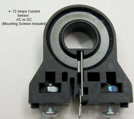
The above is a Honeywell CSLA2CD. You can see the iron core ring. It has a split in the ring at the bottom. You can see the hall effect sensor on the PCB fitted into the gap. This kind of sensor will work with DC all the way up to some maximum frequency of AC. This particular sensor is just about perfect for sensing current off a DC current into and out of a battery bank.
This sensor can be found at:
This is the response per amp per wrap around the fero-core as a function of supply voltage:
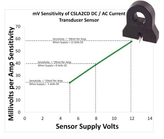
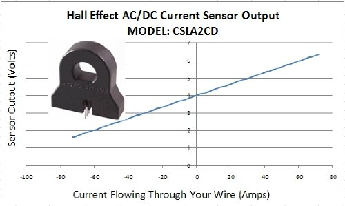
This sensor can do both forward and reverse current and zero current is set at 4V.
The arduino has a 10 bit resolution over 5 volts which means it can sense differences 4.88mV/step. At 5 volt supply the sensitivity is 24mv/Amp. This means the arduino can resolve 0.204 Amps/step. That isn’t really great, but it is doable for this project.