I’ve been watching a bunch of vlogs on YouTube and several of them have covered the importance of monitoring power, especially when “dry” camping (that’s camping without hookups). I looked into the equipment and they want like $400+ for some of it and I thought that was ridiculous. Plus you have to find somewhere to mount all the equipment, cut holes, run wires, blah, blah, blah.
I’m a nerd and love tinkering. So I thought, “Why not use an arduino as an access point and a web server along with a nRF24L01 mesh network (mySensors.org) to monitor and control stuff in the RV?” It was a decent plan and I had started figuring out how to do all that. I was going to use the arduino to serve a webpage that had a bunch of HTML5/J/ava widgets and such on it and link them using AJAX to the server so I could do interaction through a web App and keep the communication overhead low. While this may be possible, I found that there are almost no web app building tools out there contrary to what I had assumed. I am used to GUI programming using QT and thought that surely people would have an alternative or something similar for building web Apps. I couldn’t find anything good so I started searching for alternatives and found Blynk.
Blynk will do almost everything I want it to do for interaction and monitoring. I just got my Blynk server up and running on a raspberry pi zero. I configured it to act as an access point so I don’t need any internet when we are traveling. I’m very excited to start getting this project moving. Now that I know it is completely possible, I’m going to start building the sensors and adding even more cool stuff to the RV.
I’ve done some investigating into accurately measuring DC power in and out of my batteries. It is possible to use a hall effect sensor which will basically respond to the current by producing a voltage.
However, these kind of sensors aren’t all that accurate and can have a lot of drift with temperature changes. It would be nice to have something that would be more accurate.
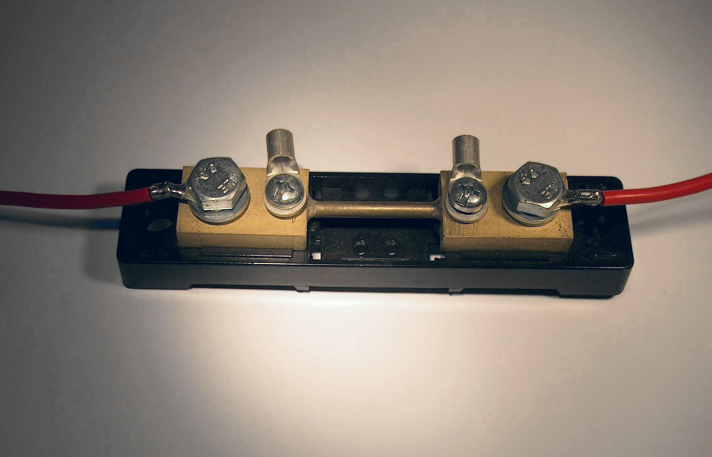
In comes the old way of doing it: a “shunt”… its basically a very low resistance resistor so it consumes very little power. Typically, thses things only have a drop of about 50mV at a the max current rating.
They tend to be a little more pricy, like $35 or so, but it may well be worth it. I found one earlier today that had a stated voltage drop of 50mV at 150A. Ohm’s law tells us that this thing has a resistance of 0.05/150=0.000333 Ohms or 333 microOhms. While that is really great for the sake of not loosing power, it does make it difficult to measure. Basically you need an amplifier circuit to measure that level of voltage as most sensors are 0-1V, 0-3.3V, or 0-5V. I suppose if I could find an SPI or I2C 12 bit 0-1V sensor, I would probably be able to get an effective 8 bits of sensing without amplification, but that still isn’t that good.
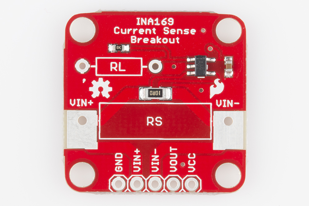
So the only really important thing is the design equation:
Vout = Is x Rs x RL / 1000
I want the range of Vout to be 0-3.3V. I don’t expect a current load on the RV higher than 50A and the load resistor has a resistance of 333 microOhms so the load resistor should have a resistance of
Figure 6: shows how to hook up two of these and use it with two A/D pins to measure bidirectional current. Basically, you hook two of them up with wires on either side of the shunt. If the current produces a negative voltage it will output 0 volts. All I need to do is calibrate the system and I’m good!
So a current shunt is about $35 and I need two of these boards at about $9/ea so I’ll have about $55 in it to measure current
So measuring voltage is the other component of measuring power. Fortunately this is really easy. All you need is a voltage divider. It is common to use a potentiometer so the value can be scaled. It is useful to have this divider in a convenient package.
This one is $7 on amazon
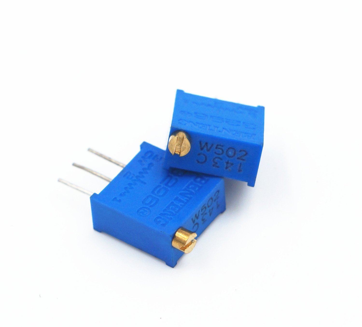
If a package isn’t necessary a cheaper option are these pots. I like this style.
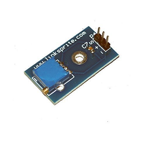
So one of the other things that would be really handy is to be able to measure the angle of the RV precicely so I can calculate the ammount of rv blocks to put under the wheels to bring it to level (no I don’t have an automatic leveling system). Again these sensors are fairly cheap. The following is a $10 sensor from sparkfun. It has 12 bit angular resolution which is more than enough. I can talk to it via I2C.
Someday, it might be cool to make an auto leveling system. I can use scissor jacks with 12v power packs.
The jacks are rated for 7500lbs, but I don’t know if the motors can produce enough torque to drive the jack up under load. I can fabricate some brackets to hold more than one motor on the jack if I have to.
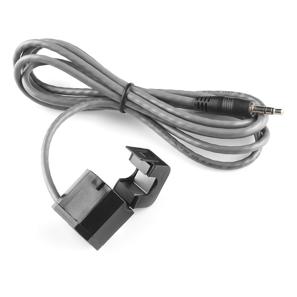
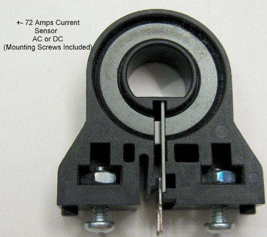
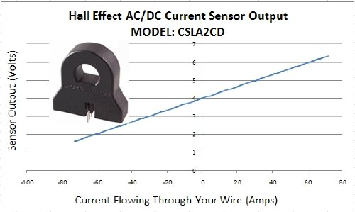
I found a relatively accurate hall effect sensor. These things work by detecting a magnetic field using a fero-magnetic material like ductile iron. When electricity flows through a wire the motion of the electrons creates a magnetic field that will wrap around the wire. The magnetic material collects some of this field. The hall effect sensor translates this magnetic field into a voltage.
The above is a Honeywell CSLA2CD. You can see the iron core ring. It has a split in the ring at the bottom. You can see the hall effect sensor on the PCB fitted into the gap. This kind of sensor will work with DC all the way up to some maximum frequency of AC. This particular sensor is just about perfect for sensing current off a DC current into and out of a battery bank.
This sensor can be found at:
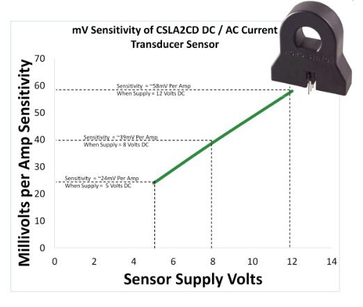
This is the response per amp per wrap around the fero-core as a function of supply voltage:
This sensor can do both forward and reverse current and zero current is set at 4V.
The arduino has a 10 bit resolution over 5 volts which means it can sense differences 4.88mV/step. At 5 volt supply the sensitivity is 24mv/Amp. This means the arduino can resolve 0.204 Amps/step. That isn’t really great, but it is doable for this project.
So the ADC of the arduino is only 10 bit or 1024 steps. However there are better ADC’s out there. A decent ADC is 16bit while scientific equipment can go up to 24 bit or higher. A 16 bit ADC will run about $7 if mounted on a breakout board like this one:
This one can sense at 4 levels, but the one I’m interested in is the -6 to 6 volt level. 16 bit resolution is 65,536 steps so the resolution of this ADC is 183 microVolts. So this gives a resolution of 7.6 miliamps per step. Thats pretty stinking good. Plus it’s a 4 channel ADC so I can get that resolution on the battery voltage meter as well. That is going to be pretty good.
However, I don’t expect that that resolution will not be totally real. I’d have to do some calculations, but I think we are at the limits of the sensitivity of the hall effect sensor.
Another note. I only have a 6V range on this thing which limits current measuring capability in 1 direction to about 60A. Typically charging is done at less than 20-30 amps, but discharge can go upwards of 100A so I’ll have to make sure that the current going out of the battery results in a drop in voltage.
This rout would result in a total cost of $7 (ADC) + $18 (Hall Sensor) for a total $25.
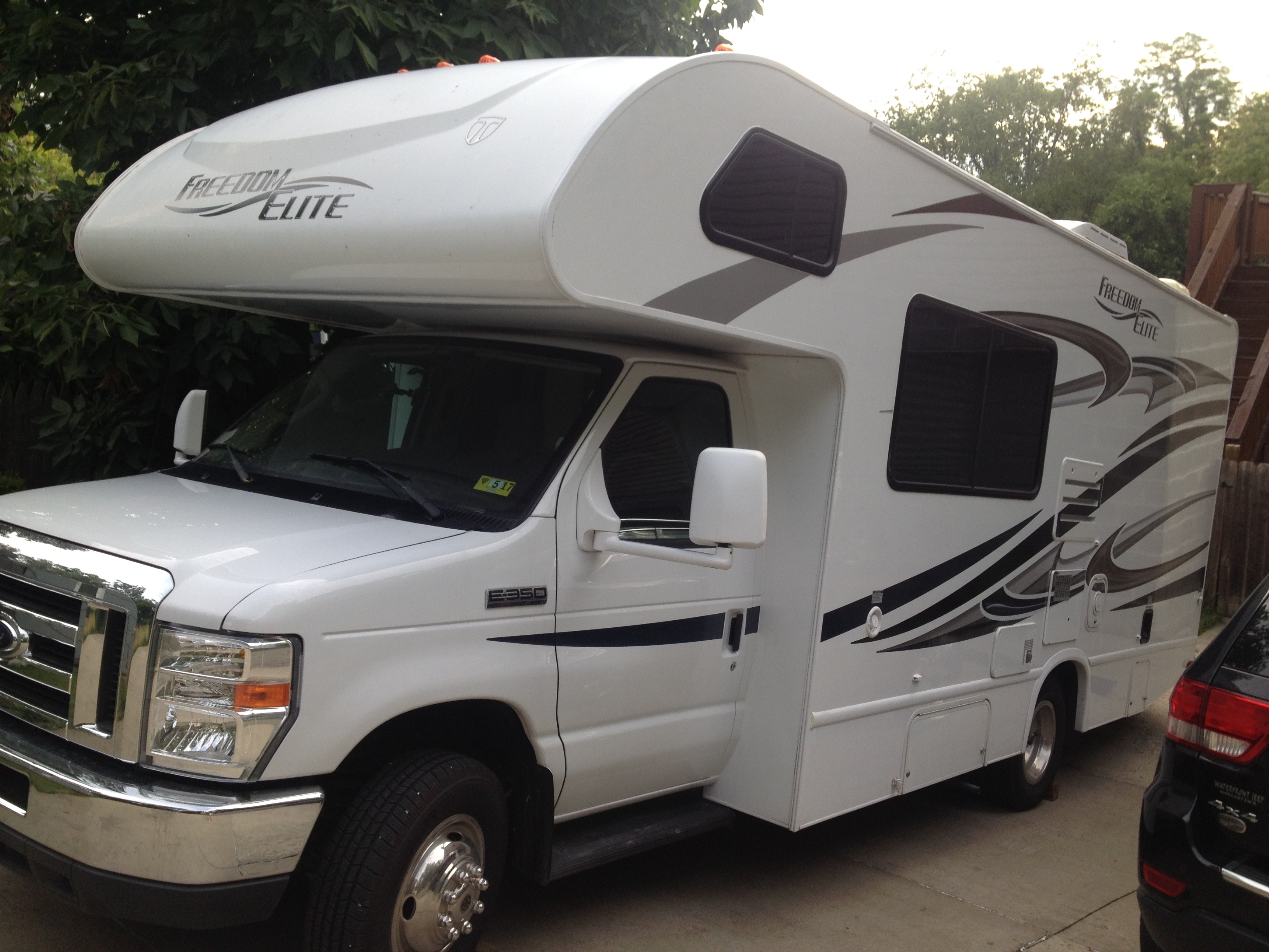
Its a 12 volt house power system. I expect charging the batteries to be in the 10-20 amp range. Discharging could be much higher depending on what loads you run. Most RV’s have an Inverter to power AC devices off the house system. Inverters can come in almost any size you want and go up to multiple KW sizes. We don’t have an inverter yet, but for our size RV I would expect that a 1.5kW inverter would be way more than enough. That size inverter will draw a minimum of 125 amps if you loaded it up and it was 100% efficient. I expect that it would really draw 130-140 amps.
So on an RV project (or any mobile project), we need to be concerned about power consumption. I can’t be consuming amps of current to do my monitoring and interaction. I’m thinking that the best way to get this going is to run a client right on the Raspberry Pi that is serving the Blynk server. I think this should be possible… maybe. It is possible to run a server and a client on the same IP if the OS can handle rerouting traffic to itself and most can. I just don’t know if the RPi can.
The other thing is that I am not really familiar with java, but I am with python. I found a repository that looks complete enough to try called pyblynk. I believe it was developed by erazor83.
So, if I can get this going, I can modify this code to work with nRF24L01 low power wireless devises to send and recieve data on that network rather than working with wifi which is about 100x more power hungry. Basically, I can connect through blynk on the rpi and then use the rpi to be a gateway to the other devises through spi or i2c.
@erazor does that sound reasonable or am I way off here?
I got the local python client running on my RPi Zero with the local Blynk server!!! It works very well!!!
Thanks a bunch @erazor for creating the repository on github for all of us to enjoy.
One thing to keep in mind. You will want to go into the lib/client.py file and change the web address of the cloud server to blynk-cloud.com. The file is old enough that it still points to cloud.blynk.cc. It will not connect to the blynk cloud service unless you change it.
That said, if you want to run the local client all you have to do is set up your local server on the RPi however you want and then go into the app, generate a token, put that token into line 21 of /examples/hw.py and change line 33 to be cConnection=blynk_client.TCP_Client(‘localhost’) instead of cConnection=blynk_client.TCP_Client(). It will connect to your blynk server and print out the messages from your blynk app. All you have to do is overwrite the On* functions to handle the events and you are golden!!!
Wow, super easy. Now you can use your standard RPi python libraries to do whatever you want!! Great!!! This is fantastic!!
I spent a lot of time today researching how I can maintain an ultra low power network and possibly implement very long lasting battery powered sensors (talking multiple years here on a single AA battery). My research elimitated doing IOT over wifi. The problem is that WiFi devises are just too power hungry. When awake and transmitting ESP8266 devises use around 120-200 mA of power. That’s really quite a lot. The strategy to extend the life of the system is to put the system to sleep, and set an timer interrupt to wake it up after X minutes after which it will take a reading, transmit, and go back to sleep. The problem with using WiFi devises is that it takes 1-6 seconds to connect to the wifi network and it will be consuming that highe amount of power all the while.
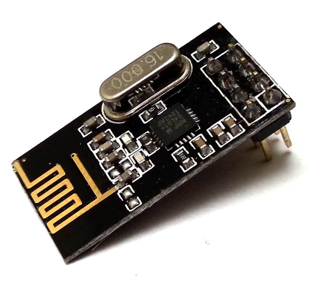
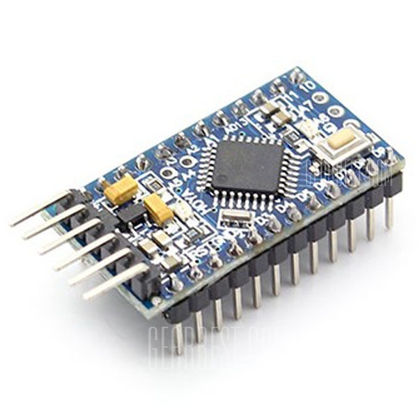
Last year I built a mesh network for my woodworking shop based around the nRF24L01 transmitter (see above). I used a network library from www.mysensors.org to create a gateway/sensor network that could detect when I turned on my tools and then switch my dust collector on if it needs it. Now I didn’t need specifically low power for this project, but I did learn that the nRF24L01 will run at about 10-15mA when transmitting and when used with an Arduino Pro Mini (see below) and when both are put to sleep, they draw less than 60 micro amps.
The other thing is that this combo is exceedingly cheap. If you find a sale somewhere you can get these things for around $1 each. I buy these things by the tens to get a good price
So then the thing is just building the bridge between the Blynk server and the mesh network. So the cool thing is that the nRF24L01’s talk on a serial port, not ethernet so it is easy to make a devise such as a raspberry pi talk on both.
So then the even cooler thing is that I found python libraries to work wtih BOTH networks. Per the previous post, I got a python Blynk client to work on the same rspberry py that the Blynk Sever is on. I also found a python wrapper for the mySensors netowrk and have seen examples of people using it on a Raspberry Pi. This means I can make my blynk client send messages over the MySensors network and reduce my power consumption by an order of magnitude!! Plus, I can end up saving money because even the cheapest WiFi devises are about twice as expensive as this setup. There are other advantages too, but these are the major ones.
Good to know people are still using the python lib and that it still works. I’ve also fixed the hostname.
There’ll probably no further development from my side on the python lib. I started implementing a server part but run out of time.
In the past we were using the nRF too and I build a tiny usb interface which already includes the network part. On USB side you simply got a serial device and you’re able to direct send and receive stuff. http://ed-solutions.de/dokuwiki/hardware:nrf:usb:at90usb
However nowadays we decided to play a bit with Bluetooth BLE, which should be usable via the python gattlib.
Thanks for the well wishes and information @erazor. It’s cool that you’re playing with BLE. I may end up using some of that. However most BLE devices are rather expensive so I have my doubts that they will be a developers go to solution for a new network. That said, there are a lot of devises out there with it and some that do cool things and have no other wireless protocol. I’d like to talk over the CAN bus to my RV system with a BLE device.
Anyhow, I’ll check out the usb library for nRF and see if I can use it. Do you know of any hardware that you can buy to directly link the USB to the nRF? It would save time if I can buy it rather than make it.
BLE / CAN shouldn’t be a problem. There are some cheap serial BLE modules on eBay which can be used to transport CAN.
Concerning the nRF, the easiest thing would be some kind of SPI/USB converter and a library written in python or whatever you find on the net. Our stuff was very specific and is badly documented.
Also take care about the voltage levels on the nRF. Using 5V on the inputs is generally a bad idea - sometimes it works but it really results in bad wireless communication. We also noticed a bad and unsteady spectrum with the modules with printed PCB antennas.
With the raspberry you already have SPI with 3.3V levels so that’d be the easiest way.
Thoughts on Controlling other major systems in the RV
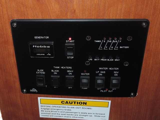
Most RV’s have some kind of control panel near the entry door. Mine is very similar to this one:
There is 12V power in this panel and ground so I have the juice I need to run what I want. The rocker switches along the bottom are simple hot side switches meaning that on one side of the switch there is 12V and the other is the leg that runs to the circuit. For momentary switches like the generator stop/start switch, slidouts, and awnings, I can connect normally open relay switches in parallel to gain control. It would be good to put a two way switch in place on the hot legs to switch control from manual to automatic. I can use a two way relay with the normally closed leg connected to the manual switch. There is room behind this panel (I think) to fit a relay board. At any rate, this is a central location at which i could put a single node on my mesh network and control most major systems.