This is a project I made using Blynk, I called it a smart fan socket, I used an ESP8266-12E, a potentiometer, and a DHT11 temperature and humidity sensor.
I hope the community likes as much as I do and have fun with this idea, simple to do and with few components you can do this project in a few minutes, please watch the video on my youtube channel.
/* ***************************************************************
* Sobre o autor deste projeto:
* Engenheiro eletronico com ampla formaçao e pratica em automação
*
* Especializado em equipamentos para cinemas
* Brasileiro natural de Sao Paulo mora atualmente em Joao Pessoa
* ***************************************************************
* Sobre este projeto:
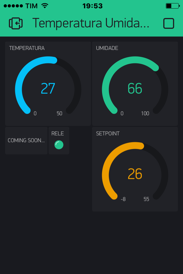
* Trata-se de uma aplicacao IoT (Internet das coisas) aproveitando
* os recursos do software Blynk dedicado a este tipo de aplicacoes,
* o objetivo foi criar uma tomada inteligente para controlar um ventilador por exemplo,
* de acordo a uma temperatura pre ajustada pelo usuario, atraves de um potenciomento.
* \\\\\\\\\\\\\\\\\\\\\\\\\\\\\\\\\\\\\\\\\\\\\\\\\\\\\\\\\\\\\\\\\\\\\\\\\\\\\\\\\\\\
* O sistema usa um ESP8266-12E da DOIT, uma sensor DHT11 que afere a umidade, e a
* temperatura ambiente, um com um contato inversor de 10A, um dysplay LCD,
* jumpers diversos, uma fonte 220VAC/9VCC 1 Amper, uma tomada norma brasileira
* 10A para embutir uma caixa plastica trabalhada para conter o projeto em si.
* \\\\\\\\\\\\\\\\\\\\\\\\\\\\\\\\\\\\\\\\\\\\\\\\\\\\\\\\\\\\\\\\\\\\\\\\\\\\\\\\\\\\\\
* Todo o projeto estara disponivel no meu website que aloja o meu Blog
* www.carloskwiek.com.br onde existem outros projetos que disponibilizo.
* \\\\\\\\\\\\\\\\\\\\\\\\\\\\\\\\\\\\\\\\\\\\\\\\\\\\\\\\\\\\\\\\\\\\\\\\\\\\\\\\\\\\\\\
* Este projeto foi testado e funcionou perfeitamente, mas não existe garantias
* que ele vá funcionar caso você coloque em pratica, fica por conta e risco de quem o faca.
* \\\\\\\\\\\\\\\\\\\\\\\\\\\\\\\\\\\\\\\\\\\\\\\\\\\\\\\\\\\\\\\\\\\\\\\\\\\\\\\\\\\\\\\\\
* ATENCAO A MANIPULACAO DE CORRENTE ELETRICA EXIGE CONHECIMENTO PREVIO,
* EU ASSUMO QUE QUEM DECIDA FAZER USO DESTE PROJETO CONHECE OS RISCOS, E
* SABE MANIPULAR COM O DEVIDO CUIDADO A REDE ELETRICA.
* \\\\\\\\\\\\\\\\\\\\\\\\\\\\\\\\\\\\\\\\\\\\\\\\\\\\\\\\\\\\\\\\\\\\\\\\\\\\\\\\\\\\\\\\\
* www.carloskwiek.com.br
* \\\\\\\\\\\\\\\\\\\\\\\\\\\\\\\\\\\\\\\\\\\\\\\\\\\\\\\\\\\\\\\\\\\\\\\\\\\\\\\\\\\\\\\\\\
* Espero que desfrute deste projeto, e minha maior recompensa.
* \\\\\\\\\\\\\\\\\\\\\\\\\\\\\\\\\\\\\\\\\\\\\\\\\\\\\\\\\\\\\\\\\\\\\\\\\\\\\\\\\\\\\\\\\\
*/
#define BLYNK_PRINT Serial // Comment this out to disable prints and save space
#include <SPI.h>
#include <ESP8266WiFi.h>
#include <BlynkSimpleEsp8266.h>
#include <SimpleTimer.h>
#include <DHT.h>
int LED = 2;
// You should get Auth Token in the Blynk App.
// Go to the Project Settings (nut icon).
char auth[] = "tokem";
// Your WiFi credentials.
// Set password to "" for open networks.
char ssid[] = "net";
char pass[] = "password";
#define DHTPIN 5 // What digital pin we're connected to
// Uncomment whatever type you're using!
#define DHTTYPE DHT11 // DHT 11
//#define DHTTYPE DHT22 // DHT 22, AM2302, AM2321
//#define DHTTYPE DHT21 // DHT 21, AM2301
DHT dht(DHTPIN, DHTTYPE);
SimpleTimer timer;
// This function sends Arduino's up time every second to Virtual Pin (5).
// In the app, Widget's reading frequency should be set to PUSH. This means
// that you define how often to send data to Blynk App.
void sendSensor()
{
float pot = A0; // Port onde esta conectado o potenciometro (Setpoint)
float valor = 0; // Variavel que armazena o valor lido no potencioment
float h = dht.readHumidity();
float t = dht.readTemperature(); // or dht.readTemperature(true) for Fahrenheit
if (isnan(h) || isnan(t)) {
Serial.println("Failed to read from DHT sensor!");
return;
}
// You can send any value at any time.
// Please don't send more that 10 values per second.
Blynk.virtualWrite(V5, h);
Blynk.virtualWrite(V6, t);
valor = analogRead (pot); // Armazena o valor de pot na variavel valor
//valor = map(valor, 0, 1023, 0, 50);
Blynk.virtualWrite(V7, valor);
Blynk.virtualWrite(V8, valor);
if (valor/21 < (t) )
{
digitalWrite(LED, LOW); //
}
else if(valor/21 >(t) )
{
digitalWrite(LED, HIGH); //
}
WidgetLED led(V9);
byte leds = digitalRead(LED);
if (leds == 1){
led.off();
}
else{
led.on();
}
WidgetLCD lcd(V10);
lcd.print(5,0, "TOMADA"); // use: (position X: 0-15, position Y: 0-1, "Message you want to print")
lcd.print(2,1, "INTELIGENTE");
// Please use timed events when LCD printintg in void loop to avoid sending too many commands
// It will cause a FLOOD Error, and connection will be dropped
}
void setup() {
{
Serial.begin(9600); // See the connection status in Serial Monitor
Blynk.begin(auth, ssid, pass);
dht.begin();
pinMode (LED,OUTPUT);
// Setup a function to be called every second
timer.setInterval(1000L, sendSensor);
}
}
void loop()
{
Blynk.run(); // Initiates Blynk
timer.run(); // Initiates SimpleTimer
}
Great app.
I want use it for read temperature from DHW cylinder, and control heating element.
My questions is: if i can use a Pt1000 or NTC (10K) encapsulated sensor (immersion sensor), and what change is necesary in IDE code.
Thanks! (I’m beginner/amateur and I have not been able to read all the posts in this forum)
I don’t know you sensor, and in this moment I am out of my office, so just next monday I can help you.
welcome to forum, and if you clic in the icon magnifying glass, can search about other topic, just put the name of you sensor and press the key enter for searching
In the UK, the traditional way of measuring hot water tank temperature is with a thermostat strapped to the side of the tank about half way down. Insulated tanks usually have a cut-out to allow direct contact between the mechanical thermostat and the tank wall.
This has the advantage of measuring the temperature half way down the tank, and as hot water rises it gives a better reading that a prpbe at the top. It also means that the thermostat doesn’t need to be waterproof.
I think i’d go for a sensor of your choice held in contact with the wall of the tank in this way.
@kwiek, @PeteKnight, I’m trying to answer you. My problem is not waterproofing of sensor, I will use an immersion sheath.
@kwiek, I wanted to ask about the difference between the temp/humid DHT11 sensor and a two-wire NTC sensor. What library to use, and what changes should be made to the sketch.
Using the Wemos D1 Mini, 10K NTC sensor and 10K resistor, I’m struggling to calibrate an NTC sensor. I tried to use the “basicntc” example in arduino 1.8.0, but I get the following error: “Error compiling for board WeMos D1 R2 & mini.”
I used a simple code (see below) to check the temperature changes (which I managed to load), I do not see any change in the resistance value when the sensor heats up or cools down:
// the value of the 'other' resistor
#define SERIESRESISTOR 10000

// What pin to connect the sensor to
#define THERMISTORPIN A0

void setup(void) {
  Serial.begin(9600);
}

void loop(void) {
  float reading;

  reading = analogRead(THERMISTORPIN);

  Serial.print("Analog reading ");
  Serial.println(reading);

  // convert the value to resistance
  reading = (1023 / reading)  - 1;     // (1023/ADC - 1)
  reading = SERIESRESISTOR / reading;  // 10K / (1023/ADC - 1)
  Serial.print("Thermistor resistance ");
  Serial.println(reading);

  delay(1000);
}
At the room temperature (23C), whit sensor on the table, on the serial monitor is displayed:
Analog reading 5.00
Thermistor resistance 49.12
Analog reading 6.00
Thermistor resistance 59.00
Analog reading 7.00
Thermistor resistance 68.90
Analog reading 7.00
Thermistor resistance 68.90
Analog reading 7.00
Thermistor resistance 68.90
Analog reading 3.00
Thermistor resistance 29.41
Analog reading 7.00
Sorry, maybe there are too many questions at once… I do not want to bother this topic
@mircea, i would highly recommend to forget the ntc or dht11 sensor (very bad quality), and use a ds18b20 (the waterproof version), that is much much better from all perspectives. you can also find available code on this forum. the analogue temperature sensors are a pain in the ass, do not bother with them.
if you live in oradea i can supply you some ds18, just send me pm. or you can also find some on olx.
I manage to use and calibrate NTC sensor Not with the code from tutorials, but was helpful.
Finally, I quit the “Wemos D1 Mini”, it seems that the A0 input did not work. I will still use “WiFi NodeMCU with ESP8266” for a daily programmable thermostat.
I will open a new post with the evolution of the project.
@Yabeng This topic was posted over a year ago and is very simply wired. Please look at the video and the code to see the needed GPIO pins. Analog A0 pin for Potentiometer, GPIO pins 2 for LED/relay and 5 DHT sensor.

 and I have not been able to read all the posts in this forum)