Hi
First I know there are so many topics about the esp and arduino regarding the water level and I read a lot but due to my level in programming is very bad and just two days ago I got new ESP8266 I start with.
I just want to get a code to my ESP8266 D1 to measure the water level with simple gauge and not in such advanced codes as I found in the forums of Blynk.
I appreciate if you help me by sending a very simple code so i can learn from it and add and modify.
There are literally millions of examples of coding on the web, along with simple tutorials and hundreds, if not more, simple examples and even explanations in this forum.
I also tend to learn from example… and I started with Blynk long before they added in the Sketch Builder… so if I was able to Google and learn to program (despite some medical issues involving staying awake long enough ), I suspect anyone can.
So, on that note… I already pointed you to exactly what you asked for… try it out.
Please see the code below and correct me if I’m wrong.
I connect the trigger of the HCR-04 to D5 and echo to D5 then the gause on Blynk app to V5 , i cant see any action from the gauge when changing the distance
#define TRIGGER 4
#define ECHO 5
// NodeMCU Pin D0 > TRIGGER | Pin D2 > ECHO
#define BLYNK_PRINT Serial // Comment this out to disable prints and save space
#include <ESP8266WiFi.h>
#include <BlynkSimpleEsp8266.h>
// You should get Auth Token in the Blynk App.
// Go to the Project Settings (nut icon).
char auth[] = "";
// Your WiFi credentials.
// Set password to "" for open networks.
char ssid[] = "my SSID";
char pass[] = "my PASS";
void setup() {
Serial.begin (9600);
Blynk.begin(auth, ssid, pass, "blynk-cloud.com", 8080);
pinMode(TRIGGER, OUTPUT);
pinMode(ECHO, INPUT);
pinMode(BUILTIN_LED, OUTPUT);
}
void loop() {
long duration, distance;
digitalWrite(TRIGGER, LOW);
delayMicroseconds(2);
digitalWrite(TRIGGER, HIGH);
delayMicroseconds(10);
digitalWrite(TRIGGER, LOW);
duration = pulseIn(ECHO, HIGH);
distance = (duration/2) / 29.1;
if (distance <=200) {
Blynk.virtualWrite(V0, 255);
}
else {
Blynk.virtualWrite(V0, 0);
}
if (distance <= 35) {
Blynk.virtualWrite(V1, 255);
}
else {
Blynk.virtualWrite(V1, 0);
}
if (distance <= 30) {
Blynk.virtualWrite(V2, 255);
}
else {
Blynk.virtualWrite(V2, 0);
}
if (distance <= 25) {
Blynk.virtualWrite(V3, 255);
}
else {
Blynk.virtualWrite(V3, 0);
}
if (distance <= 20) {
Blynk.virtualWrite(V4, 255);
}
else {
Blynk.virtualWrite(V4, 0);
}
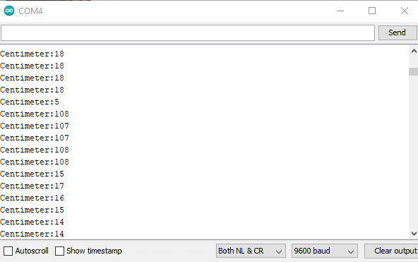
Serial.print(distance);
Serial.println("Centimeter:");
Blynk.virtualWrite(V5, distance);
delay(100);
Blynk.run();
}
OK, firstly, your choice of sensor is NOT a “simple” one in that it requires particular timing, especially when used with Blynk which has it’s own timing needs.
Secondly, the preference is to NOT use the silk screened Dx pin designations as they do differ between various types of boards.
Your sketch is using the GPIO numbering, so should you when wiring it up.
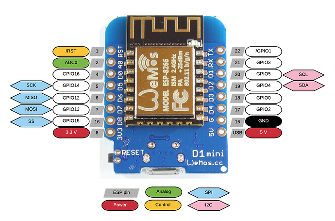
For the Wemos D1 mini… Google for yours if it is different…
Thirdly, Virtual pins are NOT directly associated with GPIO numbering, they instead refer to similarly labeled Blynk functions, commands and widgets.
If you do insist on using your ultrasonic sensor to learn with, look at this example and simply disregard the servo if you don’t have one (the gauge widget will still show positioning).
now I connect the trigger to D5 and echo to D6 without changing the code you send except the auth , SSID and password
also the gauge is connected to V0 in Blynk app but there is no measurement and same when put the gauge on V1
I couldn’t download the Blynk Qr code to my mobile since energy is 500
please advice
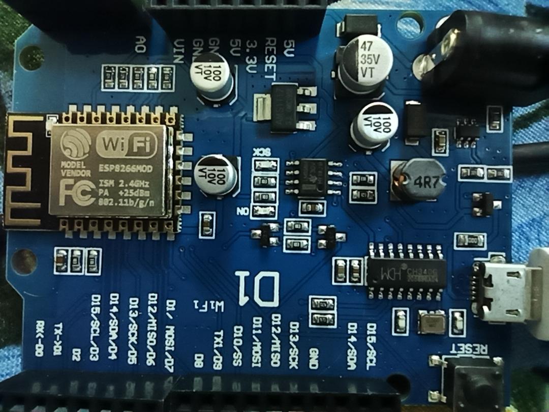
GPIO13, which connects to the Trigger Pin on your sensor, is the pin labelled “D11/MOSI/D7”
GPIO12, which connects to the Echo pin on your sensor, is the pin labelled “D12/MISO/D6”
Later in your comments you mention D5 and D6 . . . then later you mention GPIO 13 . . .
I would suggest that you remove all the blynk/wifi code from your sketch and get the sensor working with simple Serial Monitor output.
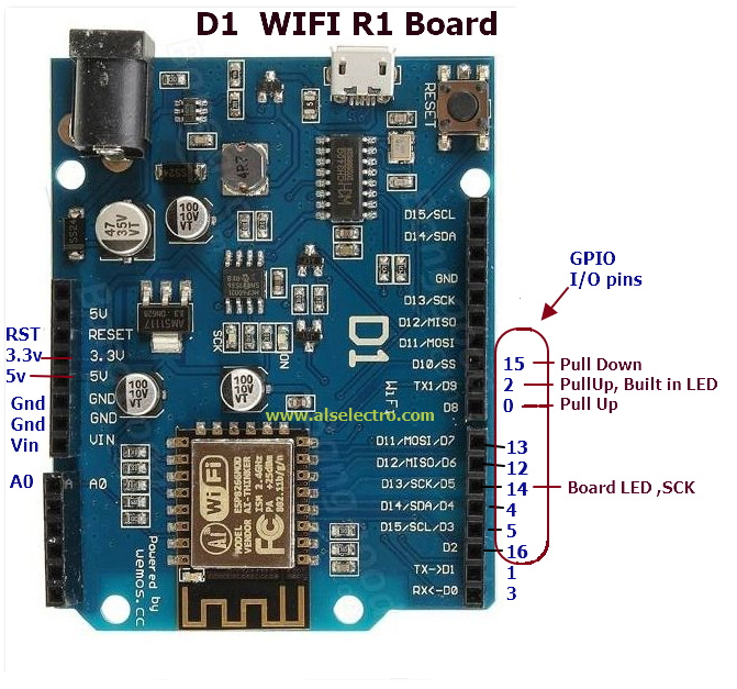
You need to clarify exactly which GPIO you have defined in your sketch, then connect the sensor to the matching physical pin on the board (printed on the board as D1, D2, D3 etc with the corresponding GPIO number on the reverse of the board.
It can be confusing but you need to be very clear on the GPIO assignment vs physical pin assignment.
Once you have the sensor operating with serial ouput, then add the wifi/blynk code and send the results to Blynk.
@Bill_Donnelly Sorry I wasn’t specific in my post ,I was referring to GTT code as below how it will be according to Wemos D1
int trigPin = 12; // D5 on Wemos D1 Mini
int echoPin = 13; // D6 on Wemos D1 Mini
int servoPin = 4; // D2 on Wemos D1 Mini
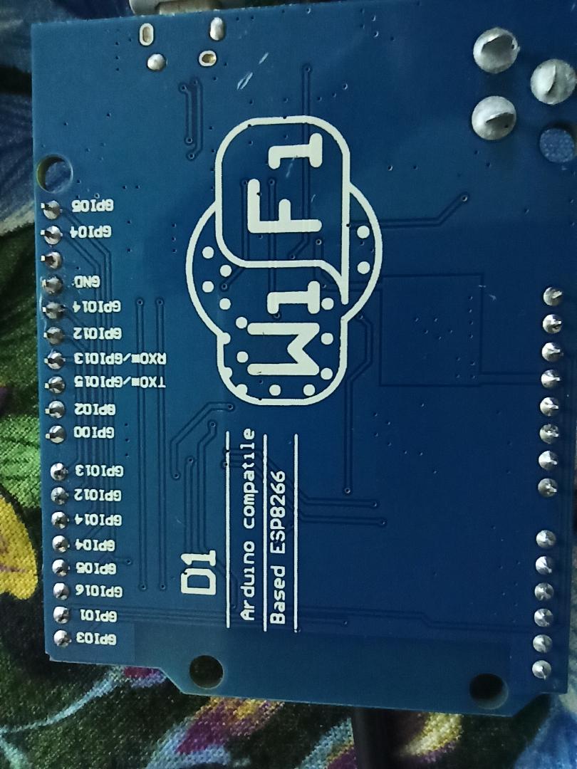
Based on the upside down image you posted, the back of your board seems to show the GPIO numbering… if so, don’t use 13 or 15 as they are probably used by the serial link to the PC?
Just pick some other GPIO pins on your board, make sure the code references the same GPIO pin numbering and test until it works.
 ), I suspect anyone can.