Device: ESP32
Communication: wifi
Purpose: switch on/off two LEDs with app and web interface.
Phone: android 12.0
Blynk server region: India
Blynk Library verion: 1.3.2
Managed to get the device online. Web interface as well as app interface are in sync with each other.
- The intention is to switch on and off LEDs connected to D26 and D33 on the ESP32 board.
- Button 1 doesn’t seem to be working.
- Button 2 switches on an internal blue LED.
- Serial monitor keeps printing message. " : 2 is reserved" which O am not printing intentionally.
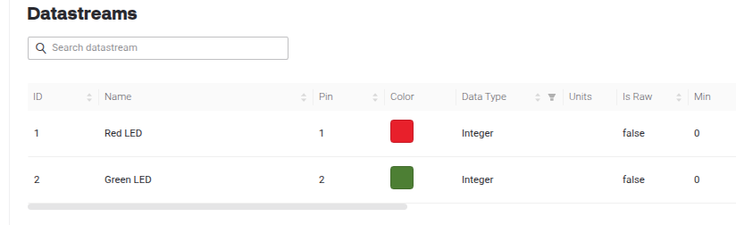
- I am using Datastream 1 and 2.
- See the images attached.
- Why won’t it correctly operate D26 and D33 on the board?
Code:
/* Fill-in information from Blynk Device Info here */
#define BLYNK_TEMPLATE_ID "..." // details are correctly given in the code
// #define BLYNK_DEVICE_NAME "..." // details are correctly given in the code
#define BLYNK_TEMPLATE_NAME "..." // details are correctly given in the code
#define BLYNK_AUTH_TOKEN "..." // details are correctly given in the code


/* Comment this out to disable prints and save space */
#define BLYNK_PRINT Serial


#include <WiFi.h>
#include <WiFiClient.h>
#include <BlynkSimpleEsp32.h>

char auth[] = BLYNK_AUTH_TOKEN;

// Your WiFi credentials.
// Set password to "" for open networks.

//Home Wifi Network
char ssid[] = "...";  // details are correctly given in the code
char pass[] = "...";  // details are correctly given in the code

BlynkTimer timer;


#define led1_pin 26
#define led2_pin 33


int led1_state = 0;
int led2_state = 0;

#define button1_vpin    V1
#define button2_vpin    V2

BLYNK_CONNECTED() {
  Blynk.syncVirtual(button1_vpin);
  Blynk.syncVirtual(button2_vpin);
}

BLYNK_WRITE(button1_vpin) {
  led1_state = param.asInt();
  digitalWrite(led1_pin, led1_state);
  Blynk.virtualWrite(led1_pin,led1_state);
  Serial.print("ledpin1 =");
  Serial.print(led1_pin);
  Serial.print(" : ");
  Serial.println(led1_state);
}

BLYNK_WRITE(button2_vpin) {
  led2_state = param.asInt();
  digitalWrite(led2_pin, led2_state);
  Blynk.virtualWrite(led2_pin,led2_state);
  Serial.print("ledpin2 =");
  Serial.print(led2_pin);
  Serial.print(" : ");
  Serial.println(led2_state);

}

void setup()
{

  Serial.begin(115200);

  pinMode(led1_pin, OUTPUT);
  pinMode(led2_pin, OUTPUT);

  Blynk.begin(auth, ssid, pass);

}
void loop()
{
  Blynk.run();
  timer.run();

  listen_push_buttons();
}

void listen_push_buttons(){
      digitalWrite(led1_pin, led1_state);
      delay(200);
      Blynk.virtualWrite(button1_vpin, led1_state);

      digitalWrite(led2_pin, led2_state);
      delay(200);
      Blynk.virtualWrite(button2_vpin, led2_state);

    }