Hi,
is it anybody here who used Shelly 2.5 with Blynk?
I like to use Shelly 2.5 with my own code in Arduino IDE but I have few questions regarding inputs on Shelly.
Maciek
There seems to be a design/manufacturing fault with the Shelly 2.5 where some of the component legs on the back of the circuit board haven’t been trimmed after soldering. This allows them to touch the Wi-Fi antenna which is stuck to the inside of the case. The antenna has an insulating film on it, but a small amount of pressure on the case will puncture the insulation and cause problems like these:
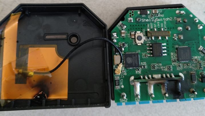

(These aren’t my photos, they are taken from the internet).
If I bought one of these the first thing I would do is to pop the cover off and take pair of snips to legs of the blue connector block pins, and to the pins in the top right hand corner of these photos.
Infact, although I’m a fan of the Shelly products, I’ll probably steer clear of the 2.5
As far as GPIOs are concerned, these are now quite well documented on the internet.
With the Shelly 1 I’ve found that there is a problem if you try to use interrupts to sense switch operations, as documented here:
I’m not sure if the 2.5 is the same or not.
Although I’ve hacked quite a lot of hardware devices in the past and happily control them with my own firmware, I’m not sure that there is as much need now, as Tasmota seems to the the De Facto way to go now.
Obviously linking Blynk and Tasmota isn’t that easy without some additional hardware/software, but as I use MQTT and Node-Red then that part is already there for me.
If you want to do power monitoring then I’d say Tasmota is definitely the way to go.
Pete.
Thanks Pete.
As I know all modules which are in polish distribution are already fixed - is a information from maker, fault was in first version, all are fixed.
That’s why I don’t like to link Tasmota and Blynk but write own code. For those purpose I need schematic or do reverse engineering to get information about hardware connections. I know on which pins are inputs and outputs, but I don’t know how it is done on electrical side.
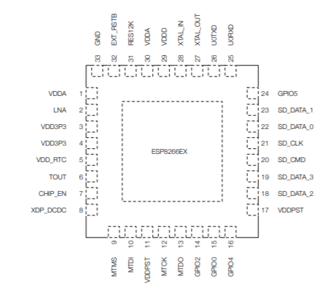
From the internet…
GPIO0 - Led1
GPIO2 - Button1
GPIO4 - Relay1
GPIO5 - Switch1
GPIO13 - Switch2
GPIO15 - Relay2
Energy metering is done by a new chip (ADE7953) connected to I2C on GPIO12/14 and IRQ on GPIO16
Temperature is measured using the Analog input
Pete.
1 Like
Thank You.
So now only left to figure out how switch 1 and 2 are connected. I think via optocoupler. But question is if I will connect Switch 1 to 230V AC value will be stable or will change 50 times per second.
Why does it matter?
That would make it a rather useless device!
Pete.
The way the input is connected is very important.
Shelly 2.5 can work with either AC or DC power supply.

When working with DC, there are no problems, giving a signal, e.g. 12V DC, to the input is not changeable in time, i.e. during program reading, as long as the voltage is on the pin, it will remain high.
In the case of AC supply, if the optocoupler itself without a rectifier is used at the input, the situation will be different.
If you give an AC signal (no matter if it is 12 or 230V AC) on an input without a rectifier and filter, the signal on the pin will change 50 times in a second. When reading the value in the program, you need to take into account these changes to distinguish whether it is interference from the switch (debounce function) or resulting from signal frequency.
That`s why I like to know type of connections to input pins to include this functionality in code. I need write simple program and check it.
I don’t think it matters exactly what circuitry is used, what matters is how it behaves when you read the value of the GPIO pin.
As you said, you need to experiment to discover the answer to this.
Pete.
Exactly, but always easier way is to look into schematic, is not necessary to make investigation ![]()
Thanks for Your help.
Maciek
I download a Blynk code into Shelly 2.5 and is working fine, I can control Relays from app. But when I like to do this without Blynk but with my own code is doesn`t work.
Any idea?
I did just a simple program which should change state of relays.
#define relay_1 16
#define relay_2 13

void setup() {

pinMode(relay_1, OUTPUT);
pinMode(relay_2, OUTPUT);
}

void loop() {

  digitalWrite(relay_1, HIGH); // sets the LED on
  delay(1000);                // waits for a second
  digitalWrite(relay_1, LOW);  // sets the LED off
  delay(1000);
  digitalWrite(relay_2, HIGH); // sets the LED on
  delay(1000);                // waits for a second
  digitalWrite(relay_2, LOW);  // sets the LED off
  delay(1000);
}

Edit-
Done.@maciekelga please edit your post, using the pencil icon at the bottom, and add triple backticks at the beginning and end of your code so that it displays correctly.
Triple backlticks look like this:
```
Pete.
The information I provided on GPIOs (which may be wrong, as I don’t have a Shelly 2.5 to verify it against) says that Relay1 is connected to GPIO4 and Relay2 is connected to GPIO15.
You’ve used different GPIOs in your code. Is this because you believe that information to be incorrect?
Pete.
Yes, but physicaly GPIO4 is a pin 16 and GPIO15 is 13.
GPIO4 - Relay1
GPIO15 - Relay2
Those GPIO are ok, becouse during control from Blynk App everything works fine.
And this is where studying schematics does you no good at all.
The IDE that compiles your code knows nothing about chip pin numbers, it takes the GPIO numbers you specify and uses them directly.
Change your code to this:
#define relay_1  4
#define relay_2 15
and it should work.
Pete.
Ok, thanks a lot, I will try.
Pete, thank You one again!
I have completely no idea why I used a physical pin instead of GPIO…really 
Now everything works fine. I can control from switch input and Blynk app. It also working when for example I turn on relay from switch input and than turn off from Blynk and vice versa.
Do You have idea what type of temperature sensor is inside? I did a reading from A0, in ambient temperature reading is around 500-600 - I assign it to V10 and display in Blynk App.
It would be nice to get as well reading from power meter, but I`m not sure if I really need it.
Currently I`m working on RGB controller on NodeMCU for LED strips, second project is Shelly both for my Home Automation IoT. After finish I will share my work on community.
According to this site:
Shelly 2.5 has a temperature sensor to prevent overheating. If the temperature goes too high, the device shuts down automatically. It also has overpowered protection and, even though not advertised, it detects earth leakage also. If the difference in current between L and N is more than 10mA it automatically shuts down.
So, I’m not sure if the sensor is of any use for measuring ambient temperature.
Pete.
Ok, I just make reading from analog pin to check if is working.
So now only left to add a code which let the program running without Wifi connection.
I need it to operate relays in Shelly locally in case of problem with Wifi/Internet, program can`t be blocked when is no wifi connection.
Hello all,
I found this old topic and I am too trying to figure out how to read power and energy use.
Someone can give some advice?
Hi,
look into:
In version 2.1 I did running power readings.