Servo doesn't function when controlled via blynk

When I try to control the servo through Blynk, it doesn’t do anything. tested with different servos and pins with no success. when I tried with the sweep example it worked just fine. so it’s not something to do with hardware.

Appreciate any help.

#define BLYNK_DEVICE_NAME "--------"
#define BLYNK_FIRMWARE_VERSION        "0.1.0"
#define BLYNK_PRINT Serial
#define APP_DEBUG
#define USE_ESP32S2_DEV_KIT
#include "BlynkEdgent.h"
#include <ESP32Servo.h>
#include <analogWrite.h>

bool forward = false;
bool backward = false;
bool left = false;
bool right = false;

#define MR1 26  //digital pin for controlling polarity motor1
#define MR2 27  //digital pin for controlling polarity motor1
#define ML1 14  //digital pin for controlling polarity motor2
#define ML2 32  //digital pin for controlling polarity motor2
const int ENA = 33;  //PWM pin to control the speed of motor1
const int ENB = 25; //PWM pin to control the speed of motor2
const int servoPinY = 4; 
const int servoPinX = 19;

Servo servoY;
Servo servoX;

void setup()
{
  Serial.begin(115200);
  pinMode(MR1, OUTPUT);
  pinMode(MR2, OUTPUT);
  pinMode(ML1, OUTPUT);
  pinMode(ML2, OUTPUT);
  pinMode(ENA, OUTPUT);
  pinMode(ENB, OUTPUT);

  servoY.attach(servoPinY);
  servoX.attach(servoPinX);

  BlynkEdgent.begin();
 
}

void loop(){
  
  BlynkEdgent.run();
  
  if (forward == true){// forward
  digitalWrite(MR1,LOW);// clockwise rotation of motor1
  digitalWrite(MR2,HIGH);
  digitalWrite(ML1,HIGH);// clockwise rotation of motor2
  digitalWrite(ML2,LOW);
  analogWrite(ENA, 255);// speed of motor1
  analogWrite(ENB, 255);// speed of motor2

  } else if (backward == true){ //backward
  digitalWrite(MR1,HIGH);
  digitalWrite(MR2,LOW);// anticlockwise rotation of motor1
  digitalWrite(ML1,LOW);
  digitalWrite(ML2,HIGH);// anticlockwise rotation of motor2
  analogWrite(ENA, 255);// speed of motor1
  analogWrite(ENB, 255);// speed of motor2

  } else if (left == true){ //left
  digitalWrite(MR1,LOW);
  digitalWrite(MR2,HIGH);
  digitalWrite(ML1,LOW);
  digitalWrite(ML2,HIGH);
  analogWrite(ENA, 255);
  analogWrite(ENB, 255);

  } else if (right == true){ // right
  digitalWrite(MR1,HIGH);
  digitalWrite(MR2,LOW);
  digitalWrite(ML1,HIGH);
  digitalWrite(ML2,LOW);
  analogWrite(ENA, 255);
  analogWrite(ENB, 255);

  } else { // stop
  digitalWrite(MR1,LOW);
  digitalWrite(MR2,HIGH);
  digitalWrite(ML1,HIGH);
  digitalWrite(ML2,LOW);
  analogWrite(ENA, 0);
  analogWrite(ENB, 0);
  }
}


BLYNK_WRITE(V0){
  if(param.asInt()==1){
    forward = true;
  }
  else{
    forward = false;
  }
}

BLYNK_WRITE(V1){
  if(param.asInt()==1){
    backward = true;
  }
  else{
    backward = false;
  }
}

BLYNK_WRITE(V2){
  if(param.asInt()==1){
    left = true;
  }
  else{
    left = false;
  }
}

BLYNK_WRITE(V3){
  if(param.asInt()==1){
    right = true;
  }
  else{
    right = false;
  }
}

BLYNK_WRITE(V4){
    servoY.write(param.asInt());
}

BLYNK_WRITE(V5){
    servoX.write(param.asInt());
}```

@Adi_s Please edit your post, using the pencil icon at the bottom, and add triple backticks at the beginning and end of your code so that it displays correctly.
Triple backticks look like this:
```

Copy and paste these if you can’t find the correct symbol on your keyboard.

Pete.

1 Like

sorry i fixed it

First of all, you should read this
https://docs.blynk.io/en/legacy-platform/legacy-articles/keep-your-void-loop-clean

thank you ill look into fixing that

It would probably be helpful if you posted the EXACT code that you used with this example, and if you didn’t use the same pins as in your Blynk sketch above then change your sweep example to use these pins and re-test if first.

Details of the type of servo controller and types of servo that you are using, along with details of how they are wired would probably also be useful.

Have you changed the Settings.h tab at all? If not then you have a conflict with pin 19…

#elif defined(USE_ESP32S2_DEV_KIT)

  #define BOARD_BUTTON_PIN            0
  #define BOARD_BUTTON_ACTIVE_LOW     true

  #define BOARD_LED_PIN               19
  #define BOARD_LED_INVERSE           false
  #define BOARD_LED_BRIGHTNESS        128

#else

Pete.

yes, this is the exact code. I changed the settings led pin to pin 18 to avoid conflict. Servo positive is connected to 5v and the signal is connected directly to esp32 pin 19. servo is Tower Pro SG90.

here is the settings

 /*
 * Board configuration (see examples below).
 */

#if defined(USE_NODE_MCU_BOARD) || defined(USE_WEMOS_D1_MINI)

  #define BOARD_BUTTON_PIN            0
  #define BOARD_BUTTON_ACTIVE_LOW     true

  #define BOARD_LED_PIN               16
  #define BOARD_LED_INVERSE           true
  #define BOARD_LED_BRIGHTNESS        255

#elif defined(USE_SPARKFUN_BLYNK_BOARD)

  #define BOARD_BUTTON_PIN            0
  #define BOARD_BUTTON_ACTIVE_LOW     true

  #define BOARD_LED_PIN_WS2812        4
  #define BOARD_LED_BRIGHTNESS        64

#elif defined(USE_WITTY_CLOUD_BOARD)

  #define BOARD_BUTTON_PIN            4
  #define BOARD_BUTTON_ACTIVE_LOW     true

  #define BOARD_LED_PIN_R             15
  #define BOARD_LED_PIN_G             12
  #define BOARD_LED_PIN_B             13
  #define BOARD_LED_INVERSE           false
  #define BOARD_LED_BRIGHTNESS        64

#else

  #warning "Custom board configuration is used"

  #define BOARD_BUTTON_PIN            0                     // Pin where user button is attached
  #define BOARD_BUTTON_ACTIVE_LOW     true                  // true if button is "active-low"

  #define BOARD_LED_PIN               4                     // Set LED pin - if you have a single-color LED attached
  //#define BOARD_LED_PIN_R           15                    // Set R,G,B pins - if your LED is PWM RGB
  //#define BOARD_LED_PIN_G           12
  //#define BOARD_LED_PIN_B           13
  //#define BOARD_LED_PIN_WS2812      4                     // Set if your LED is WS2812 RGB
  #define BOARD_LED_INVERSE           false                 // true if LED is common anode, false if common cathode
  #define BOARD_LED_BRIGHTNESS        64                    // 0..255 brightness control

#endif


/*
 * Advanced options
 */

#define BUTTON_HOLD_TIME_INDICATION   3000
#define BUTTON_HOLD_TIME_ACTION       10000
#define BUTTON_PRESS_TIME_ACTION      50

#define BOARD_PWM_MAX                 1023

#if !defined(CONFIG_DEVICE_PREFIX)
#define CONFIG_DEVICE_PREFIX          "Blynk"
#endif
#if !defined(CONFIG_AP_URL)
#define CONFIG_AP_URL                 "blynk.setup"
#endif
#if !defined(CONFIG_DEFAULT_SERVER)
#define CONFIG_DEFAULT_SERVER         "blynk.cloud"
#endif
#if !defined(CONFIG_DEFAULT_PORT)
#define CONFIG_DEFAULT_PORT           443
#endif

#define WIFI_CLOUD_MAX_RETRIES        500
#define WIFI_NET_CONNECT_TIMEOUT      50000
#define WIFI_CLOUD_CONNECT_TIMEOUT    50000
#define WIFI_AP_IP                    IPAddress(192, 168, 4, 1)
#define WIFI_AP_Subnet                IPAddress(255, 255, 255, 0)
//#define WIFI_CAPTIVE_PORTAL_ENABLE

#define USE_TICKER
//#define USE_TIMER_ONE
//#define USE_TIMER_THREE
//#define USE_TIMER_FIVE
//#define USE_PTHREAD

#define BLYNK_NO_DEFAULT_BANNER

#if defined(APP_DEBUG)
  #define DEBUG_PRINT(...)  BLYNK_LOG1(__VA_ARGS__)
  #define DEBUG_PRINTF(...) BLYNK_LOG(__VA_ARGS__)
#else
  #define DEBUG_PRINT(...)
  #define DEBUG_PRINTF(...)
#endif

        ```

and here is the sweep example i used, the one that worked.

#include <Servo.h>

static const int servoPin = 19;

Servo servo1;

void setup() {
    Serial.begin(115200);
    servo1.attach(servoPin);
}

void loop() {
    for(int posDegrees = 0; posDegrees <= 180; posDegrees++) {
        servo1.write(posDegrees);
        Serial.println(posDegrees);
        delay(20);
    }

    for(int posDegrees = 180; posDegrees >= 0; posDegrees--) {
        servo1.write(posDegrees);
        Serial.println(posDegrees);
        delay(20);
    }
}

This is the Settings.h file for an Edgent_ESP8266 example, not an ESP32 example.

Pete.

oops, I pasted the wrong one.

/*
 * Board configuration (see examples below).
 */

#if defined(USE_WROVER_BOARD)

  #define BOARD_BUTTON_PIN            15
  #define BOARD_BUTTON_ACTIVE_LOW     true

  #define BOARD_LED_PIN_R             0
  #define BOARD_LED_PIN_G             2
  #define BOARD_LED_PIN_B             4
  #define BOARD_LED_INVERSE           false
  #define BOARD_LED_BRIGHTNESS        128

#elif defined(USE_TTGO_T7)

  // This board does not have a built-in button
  // Connect a button to gpio0 <> GND
  #define BOARD_BUTTON_PIN            0
  #define BOARD_BUTTON_ACTIVE_LOW     true

  #define BOARD_LED_PIN               18
  #define BOARD_LED_INVERSE           false
  #define BOARD_LED_BRIGHTNESS        64

#elif defined(USE_ESP32C3_DEV_MODULE)

  #define BOARD_BUTTON_PIN            9
  #define BOARD_BUTTON_ACTIVE_LOW     true

  #define BOARD_LED_PIN_WS2812        8
  #define BOARD_LED_INVERSE           false
  #define BOARD_LED_BRIGHTNESS        32

#elif defined(USE_ESP32S2_DEV_KIT)

  #define BOARD_BUTTON_PIN            0
  #define BOARD_BUTTON_ACTIVE_LOW     true

  #define BOARD_LED_PIN               18
  #define BOARD_LED_INVERSE           false
  #define BOARD_LED_BRIGHTNESS        128

#else

  #warning "Custom board configuration is used"

  #define BOARD_BUTTON_PIN            0                     // Pin where user button is attached
  #define BOARD_BUTTON_ACTIVE_LOW     true                  // true if button is "active-low"

  #define BOARD_LED_PIN               4                     // Set LED pin - if you have a single-color LED attached
  //#define BOARD_LED_PIN_R           15                    // Set R,G,B pins - if your LED is PWM RGB
  //#define BOARD_LED_PIN_G           12
  //#define BOARD_LED_PIN_B           13
  //#define BOARD_LED_PIN_WS2812      4                     // Set if your LED is WS2812 RGB
  #define BOARD_LED_INVERSE           false                 // true if LED is common anode, false if common cathode
  #define BOARD_LED_BRIGHTNESS        64                    // 0..255 brightness control

#endif


/*
 * Advanced options
 */

#define BUTTON_HOLD_TIME_INDICATION   3000
#define BUTTON_HOLD_TIME_ACTION       10000
#define BUTTON_PRESS_TIME_ACTION      50

#define BOARD_PWM_MAX                 1023

#define BOARD_LEDC_CHANNEL_1          1
#define BOARD_LEDC_CHANNEL_2          2
#define BOARD_LEDC_CHANNEL_3          3
#define BOARD_LEDC_TIMER_BITS         10
#define BOARD_LEDC_BASE_FREQ          12000

#if !defined(CONFIG_DEVICE_PREFIX)
#define CONFIG_DEVICE_PREFIX          "Blynk"
#endif
#if !defined(CONFIG_AP_URL)
#define CONFIG_AP_URL                 "blynk.setup"
#endif
#if !defined(CONFIG_DEFAULT_SERVER)
#define CONFIG_DEFAULT_SERVER         "blynk.cloud"
#endif
#if !defined(CONFIG_DEFAULT_PORT)
#define CONFIG_DEFAULT_PORT           443
#endif

#define WIFI_CLOUD_MAX_RETRIES        500
#define WIFI_NET_CONNECT_TIMEOUT      50000
#define WIFI_CLOUD_CONNECT_TIMEOUT    50000
#define WIFI_AP_IP                    IPAddress(192, 168, 4, 1)
#define WIFI_AP_Subnet                IPAddress(255, 255, 255, 0)
//#define WIFI_CAPTIVE_PORTAL_ENABLE

//#define USE_TICKER
//#define USE_TIMER_ONE
//#define USE_TIMER_THREE
//#define USE_TIMER_FIVE
#define USE_PTHREAD

#define BLYNK_NO_DEFAULT_BANNER

#if defined(APP_DEBUG)
  #define DEBUG_PRINT(...)  BLYNK_LOG1(__VA_ARGS__)
  #define DEBUG_PRINTF(...) BLYNK_LOG(__VA_ARGS__)
#else
  #define DEBUG_PRINT(...)
  #define DEBUG_PRINTF(...)
#endif

It’s difficult to comment on your sketch until we see a version where you’ve cleaned-up the void loop.

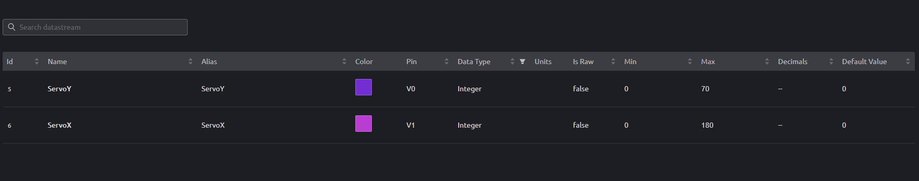
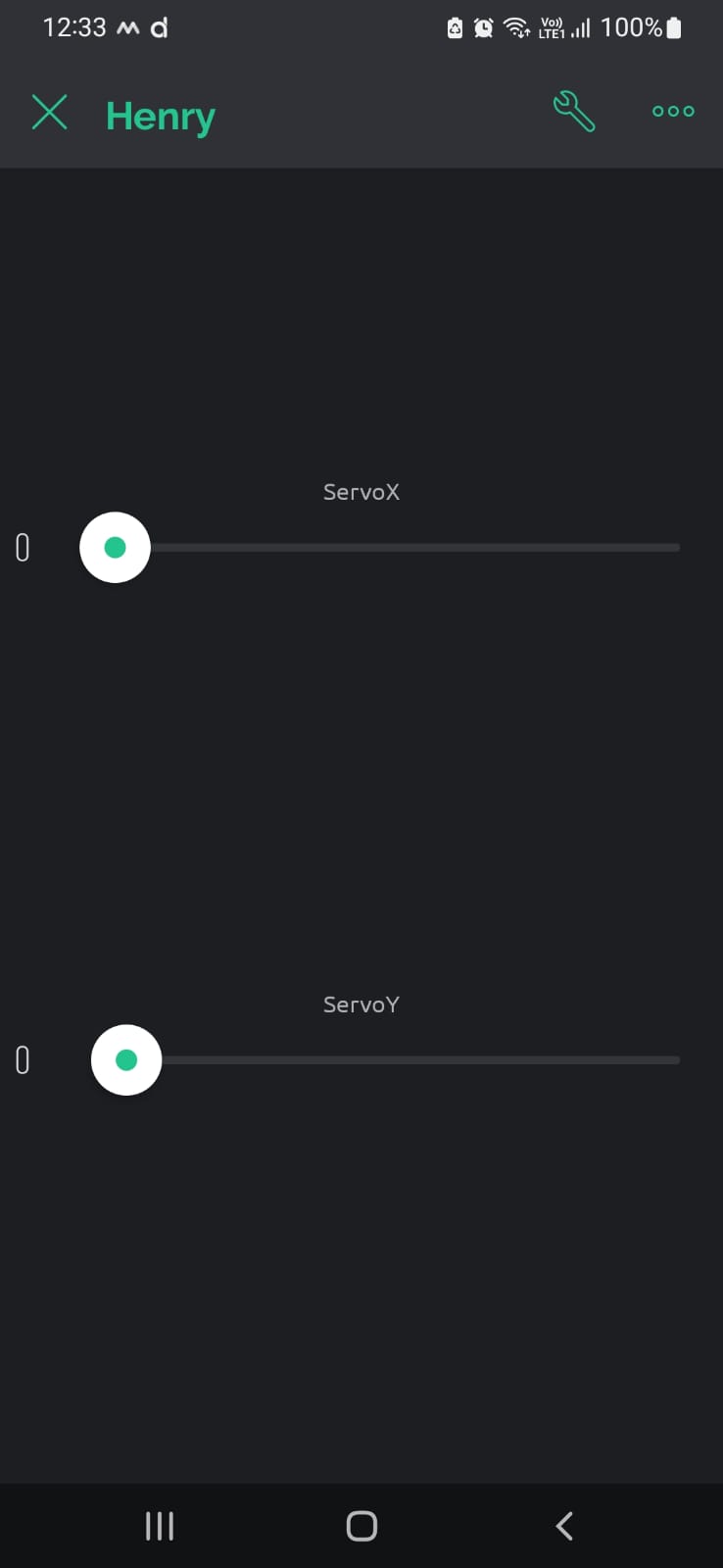
What sort of widget do you have attached to virtual pins V4 and V5, and what are the Min/Max values for the V4 and V5 datastreams (defined in the web console > template > datastreams screen)?

Pete.

I cleaned up the sketch a bit.

#define BLYNK_TEMPLATE_ID "-----------"
#define BLYNK_DEVICE_NAME "--------"
#define BLYNK_FIRMWARE_VERSION        "0.1.0"
#define BLYNK_PRINT Serial
#define APP_DEBUG
#define USE_ESP32S2_DEV_KIT
#include "BlynkEdgent.h"
#include <Servo.h>

const int servoPinY = 4; 
const int servoPinX = 19;

Servo servoY;
Servo servoX;

void setup()
{
  Serial.begin(115200);
  servoY.attach(servoPinY);
  servoX.attach(servoPinX);
  BlynkEdgent.begin();
 
}

void loop(){
  BlynkEdgent.run();
}

BLYNK_WRITE(V0){
    servoY.write(param.asInt());
}

BLYNK_WRITE(V1){
    servoX.write(param.asInt());
}

here is the virtual pin page and widgets

And now you don’t have a board type in your sketch so the custom configuration is being used, and you now have a GPIO4 conflict.

Have you re-run the “sweep” example using pins 4 and 19 to prove that it still works and that you haven’t killed these pins on your ESP32 ?

Pete.

The sketch has the USE_ESP32S2_DEV_KIT defined so I’m confused as to why u mentioned the conflict. and yes I checked the pin 4 and 19 on sweep and they worked just fine. but both pins doesn’t seem to work when used in the blynk sketch and nor does any other pins.

Apologies, I didn’t spot that tucked away in there.

Pete.

that’s okay. I suspect this issue has something to do with either the blynk side of things or some type of incompatibility with the servo library and blynk. I think…