First of all, my english is not very good so I get help from google translate.
I have a lamp project for my room.
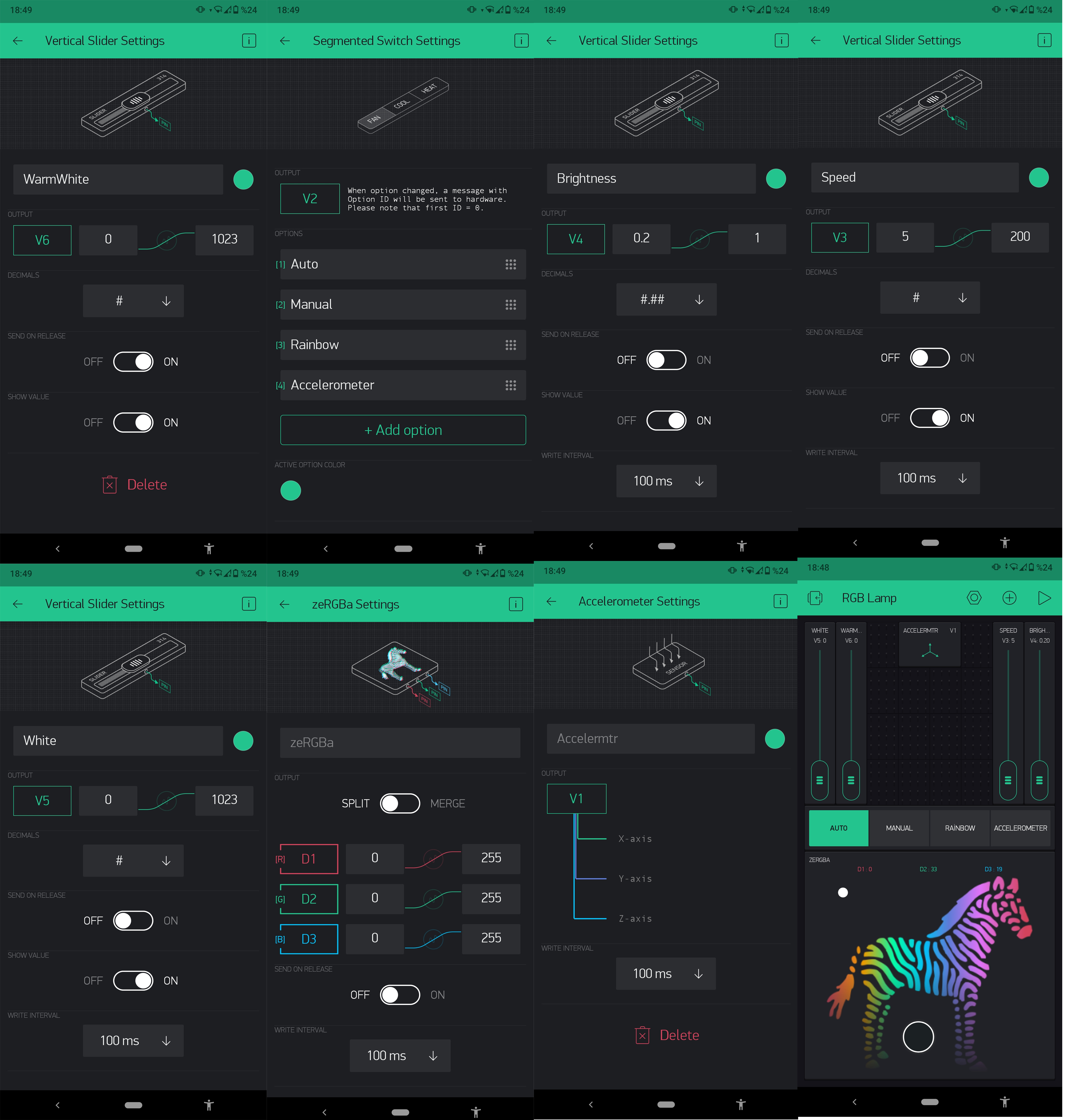
I will use RGB strip leds for this project.
I want to have 4 mods in this lamp. Mod1 (AUTO): The lamp will use the HC-SR505 mini PIR sensor. When the sensor detects motion, the lamp will light for 30 seconds and go off. And I’m going to use the RTC widget. It will light for 10 seconds when the clock is 00:00. The lamp should always use this mode when it first starts.
Mod2 (Manual):
2 sliders(V5, V6) will be used. For the lamp to turn white and warm white. In addition, zeRGBa will be used.
Mod3 (Rainbow): I found a rgb led code on the arduino forum 4 years ago. I want it to run this code. I want to control the brightness and delay variables in the code using the slider(V3, V4).
Mod4 (Accelerometer): This mode will detect phone movements and enable the lamp to light in different colors. This code is ready but it doesn’t work when you put it in mod. Continuous connection with blynk server is lost.
I think what I want to do is simple. I cannot fully understand how to use virtual pins. I cannot use virtual pins with segmented switch.
I couldn’t run loops correctly
I have been researching for days and trying many codes. But I was not able to run it fully.
I want to use ds18b20 in the system. It has to work continuously. It should show the temperature continuously.
This is very important to me and I need help. I did a lot of research on the internet. I have tried many codes. I couldn’t make it work properly. I need people to really help me with this project. I would be happy if you could show me how to do it with examples.
If I can do this correctly, I will share it with other people.
Codes are ready (Mode1, mode2, mode 3, mode 4)
All codes are working correctly. But I can’t run them all together. (Mode1, mode2, mode3, mode4)
Now let me show you the screenshot of the application and a few codes I have tried.
Thanks for answering
I tried a lot of things. I was trying to find the right one by trying. How can I run the codes together. Is there an example for me?
No, this is a fairly bespoke requirement, so you need to write it yourself.
You don’t run one callback within another. You could use the first callback (V2) to set a “Mode” variable then ignore any accelerometer input from V2 unless the “Mode” is set to 3 (accelerometer).
Yes, provided you format your code correctly, using triple backticks at the beginning and end of your code rather than blockquotes.
Triple backticks look like this:
```
No, I’ve already explained that you can’t have one BLYNK_WRITE(vPin) within another.
I did what I wanted. There may be some mistakes. I encountered a minor problem and ask for help. I just added Mod4. Mod4 rainbow effect. Before I added Mod4, I could switch modes. Now when I select MOD4, I cannot select another mode. Could you help?
#define BLYNK_PRINT Serial

#define  R_PIN  4  // Red LED
#define  G_PIN  5  // Green LED
#define  B_PIN  16  // Blue LED
#define  MIN_RGB_VALUE  10   // no smaller than 0.
#define  MAX_RGB_VALUE  255  // no bigger than 255.
#define  TRANSITION_DELAY  70   // in milliseconds, between individual light changes
#define  WAIT_DELAY        500
#include <ESP8266WiFi.h>
#include <BlynkSimpleEsp8266.h>

// You should get Auth Token in the Blynk App.
// Go to the Project Settings (nut icon).
char auth[] = "***auth***";

// Your WiFi credentials.
// Set password to "" for open networks.
char ssid[] = "WWW";
char pass[] = "PPP";
int x;
int y;
int z;
int p;
int a;
int b;
int c;
int r;
int g;
int m;
int k;
int dx;
int dy;
int dz;

typedef struct
{
  byte  x, y, z;
} coord;

static coord  v;

const coord vertex[] =
{

  {0, 0, 0},
  {0, 1, 0},
  {0, 1, 1},
  {0, 0, 1},
  {1, 0, 0},
  {1, 1, 0},
  {1, 1, 1},
  {1, 0, 1}
};

const byte path[] =
{
  0x01, 0x23, 0x76, 0x54, 0x03, 0x21, 0x56, 0x74,
  0x13, 0x64, 0x16, 0x02, 0x75, 0x24, 0x35, 0x17, 0x25, 0x70,
};

#define  MAX_PATH_SIZE  (sizeof(path)/sizeof(path[0]))

BLYNK_WRITE(V2)
{
  k = param.asInt();
  p=map(k,0,1023,0,255);
}

BLYNK_WRITE(V3)
{
    x = param[0].asInt();
    y = param[1].asInt();
    z = param[2].asInt();
    a=map(x,-10, 10, 0, 1023);
    b=map(y,-10, 10, 0, 1023);
    c=map(z,-10, 10, 0, 1023);
}
BLYNK_WRITE(V4)
{
    r = param[0].asInt();
    g = param[1].asInt();
    m = param[2].asInt();

}


void traverse(int dx, int dy, int dz)
{
  if ((dx == 0) && (dy == 0) && (dz == 0))
    return;

  for (int i = 0; i < MAX_RGB_VALUE-MIN_RGB_VALUE; i++, v.x += dx, v.y += dy, v.z += dz)
  {

    analogWrite(R_PIN, v.x);
    analogWrite(G_PIN, v.y);
    analogWrite(B_PIN, v.z);

    delay(TRANSITION_DELAY);
  }

  delay(WAIT_DELAY);
}

void loop3()
{
  int    v1, v2=0;


  v.x = (vertex[v2].x ? MAX_RGB_VALUE : MIN_RGB_VALUE);
  v.y = (vertex[v2].y ? MAX_RGB_VALUE : MIN_RGB_VALUE);
  v.z = (vertex[v2].z ? MAX_RGB_VALUE : MIN_RGB_VALUE);


  for (int i = 0; i < 2*MAX_PATH_SIZE; i++)
  {

    v1 = v2;
    if (i&1)
      v2 = path[i>>1] & 0xf;
    else
      v2 = path[i>>1] >> 4;
    traverse(vertex[v2].x-vertex[v1].x,
             vertex[v2].y-vertex[v1].y,
             vertex[v2].z-vertex[v1].z);
  }
}

void acce(int a, int b, int c){

    analogWrite(4, a);
    analogWrite(5, b);
    analogWrite(16, c);
}
void zebra(int r, int g, int m){

    analogWrite(4, r);
    analogWrite(5, g);
    analogWrite(16, m);
}
void parlak(int par)
{

  analogWrite(5,k);
  analogWrite(4,k);
  analogWrite(16,k);
}


BLYNK_WRITE(V1)
{
  int mod = param.asInt();
  if( mod == 1)
  {
    parlak(k);
    Blynk.run();
    int mod = 0;
    Blynk.syncVirtual(V1);
  }
  if(mod == 2){
    acce(a,b,c);
    Blynk.run();
    int mod = 0;
    Blynk.syncVirtual(V1);
  }
  if(mod == 3){
    zebra(r,g,m);
    Blynk.run();
    int mod = 0;
    Blynk.syncVirtual(V1);
}
 if(mod == 4){
    traverse(dx,dy,dz);
    loop3();
    Blynk.run();
    int mod = 0;
    Blynk.syncVirtual(V1);
}
}

void setup()
{
  // Debug console
  Serial.begin(9600);

  Blynk.begin(auth, ssid, pass);
}

void loop()
{
  Blynk.run();
}
I made some copy from this project;
Arduino Rainbow Code
RGB LED - Automatic Smooth Color Cycling

Marco Colli
April 2012

Uses the properties of the RGB Colour Cube
The RGB colour space can be viewed as a cube of colour. If we assume a cube of dimension 1, then the
coordinates of the vertices for the cubve will range from (0,0,0) to (1,1,1) (all black to all white).
The transitions between each vertex will be a smooth colour flow and we can exploit this by using the
path coordinates as the LED transition effect.
*/
// Output pins for PWM
#define  R_PIN  3  // Red LED
#define  G_PIN  5  // Green LED
#define  B_PIN  6  // Blue LED

// Constants for readability are better than magic numbers
// Used to adjust the limits for the LED, especially if it has a lower ON threshold
#define  MIN_RGB_VALUE  10   // no smaller than 0.
#define  MAX_RGB_VALUE  255  // no bigger than 255.

// Slowing things down we need ...
#define  TRANSITION_DELAY  70   // in milliseconds, between individual light changes
#define  WAIT_DELAY        500  // in milliseconds, at the end of each traverse
//
// Total traversal time is ((MAX_RGB_VALUE - MIN_RGB_VALUE) * TRANSITION_DELAY) + WAIT_DELAY
// eg, ((255-0)*70)+500 = 18350ms = 18.35s

// Structure to contain a 3D coordinate
typedef struct
{
  byte  x, y, z;
} coord;

static coord  v; // the current rgb coordinates (colour) being displayed

/*
Vertices of a cube

    C+----------+G
    /|        / |
  B+---------+F |
   | |       |  |    y
   |D+-------|--+H   ^  7 z
   |/        | /     | /
  A+---------+E      +--->x

*/
const coord vertex[] =
{
//x  y  z      name
  {0, 0, 0}, // A or 0
  {0, 1, 0}, // B or 1
  {0, 1, 1}, // C or 2
  {0, 0, 1}, // D or 3
  {1, 0, 0}, // E or 4
  {1, 1, 0}, // F or 5
  {1, 1, 1}, // G or 6
  {1, 0, 1}  // H or 7
};

/*
A list of vertex numbers encoded 2 per byte.
Hex digits are used as vertices 0-7 fit nicely (3 bits 000-111) and have the same visual
representation as decimal, so bytes 0x12, 0x34 ... should be interpreted as vertex 1 to
v2 to v3 to v4 (ie, one continuous path B to C to D to E).
*/
const byte path[] =
{
  0x01, 0x23, 0x76, 0x54, 0x03, 0x21, 0x56, 0x74,  // trace the edges
  0x13, 0x64, 0x16, 0x02, 0x75, 0x24, 0x35, 0x17, 0x25, 0x70,  // do the diagonals
};

#define  MAX_PATH_SIZE  (sizeof(path)/sizeof(path[0]))  // size of the array

void setup()
{
  pinMode(R_PIN, OUTPUT);   // sets the pins as output
  pinMode(G_PIN, OUTPUT);
  pinMode(B_PIN, OUTPUT);
}

void traverse(int dx, int dy, int dz)
// Move along the colour line from where we are to the next vertex of the cube.
// The transition is achieved by applying the 'delta' value to the coordinate.
// By definition all the coordinates will complete the transition at the same
// time as we only have one loop index.
{
  if ((dx == 0) && (dy == 0) && (dz == 0))   // no point looping if we are staying in the same spot!
    return;

  for (int i = 0; i < MAX_RGB_VALUE-MIN_RGB_VALUE; i++, v.x += dx, v.y += dy, v.z += dz)
  {
    // set the colour in the LED
    analogWrite(R_PIN, v.x);
    analogWrite(G_PIN, v.y);
    analogWrite(B_PIN, v.z);

    delay(TRANSITION_DELAY);  // wait fot the transition delay
  }

  delay(WAIT_DELAY);          // give it an extra rest at the end of the traverse
}

void loop()
{
  int    v1, v2=0;    // the new vertex and the previous one

  // initialise the place we start from as the first vertex in the array
  v.x = (vertex[v2].x ? MAX_RGB_VALUE : MIN_RGB_VALUE);
  v.y = (vertex[v2].y ? MAX_RGB_VALUE : MIN_RGB_VALUE);
  v.z = (vertex[v2].z ? MAX_RGB_VALUE : MIN_RGB_VALUE);

  // Now just loop through the path, traversing from one point to the next
  for (int i = 0; i < 2*MAX_PATH_SIZE; i++)
  {
    // !! loop index is double what the path index is as it is a nybble index !!
    v1 = v2;
    if (i&1)  // odd number is the second element and ...
      v2 = path[i>>1] & 0xf;  // ... the bottom nybble (index /2) or ...
    else      // ... even number is the first element and ...
      v2 = path[i>>1] >> 4;  // ... the top nybble

    traverse(vertex[v2].x-vertex[v1].x,
             vertex[v2].y-vertex[v1].y,
             vertex[v2].z-vertex[v1].z);
  }
}
Your function is starving the Blynk library of processor time, so it can’t check-in with the Blynk server , which leads to the disconnection.
In addition, having
after each of the mode execution blocks of code has the effect of immediately re-triggering the BLYNK_WRITE(V1) function, which isn’t really the best way of looping the code - assuming that’s what you’re trying to achieve.