New to the Arduino and Blynk world and in need of some help.
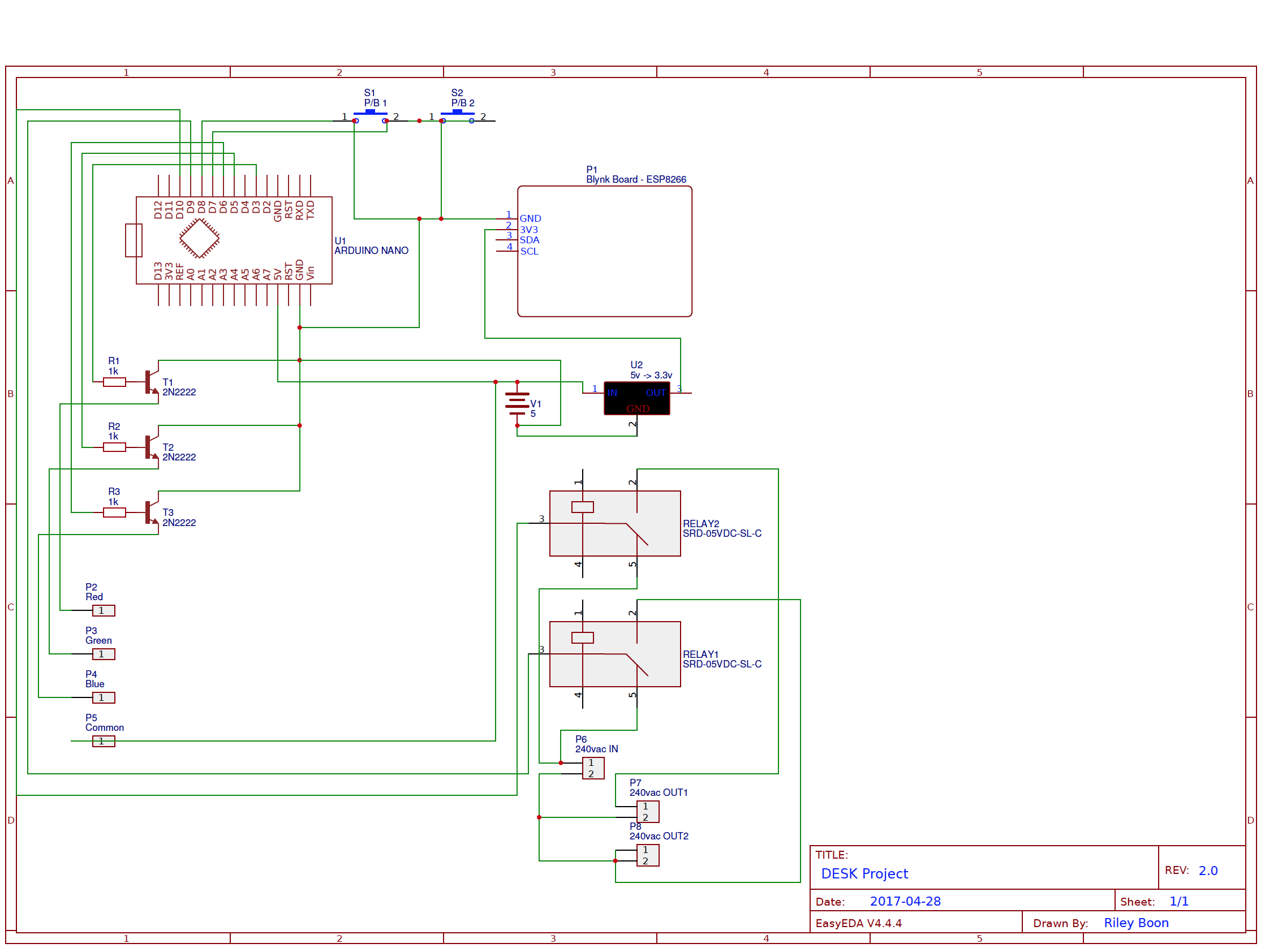
I am using an Arduino Nano and an ESP8266 to control this project. I am also using the Blynk app for iOS.
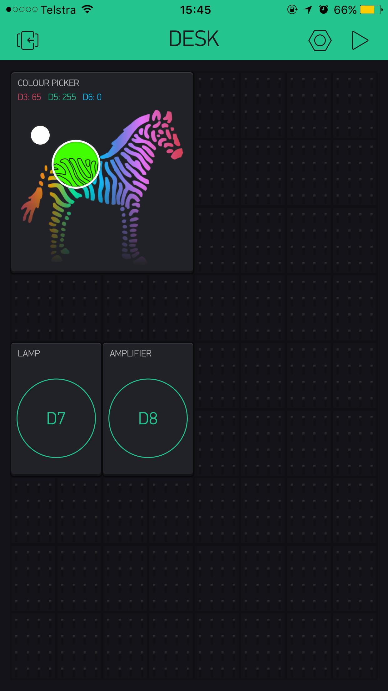
The plan is to control an RGB LED strip with the zeRGBa widget, and to also control two relay’s for lamps, which can be controlled via two buttons on the Blynk app (screenshot below) and also two momentary push buttons mounted to the side of my desk.
The current code that I have will turn the relay on and off via the push buttons only. I need the app to be able to tell me what state these outputs are currently in, and to also control them and the LED strip.
Here is the code I have so far. As I said, I am only new so I have no idea what I’m doing. Any suggestions would be really helpful.
    define BLYNK_PRINT Serial  // BLYNK Code
    include <ESP8266_Lib.h>
    include <BlynkSimpleShieldEsp8266.h>

    const int red = 3;      // LED strip red
    const int green = 5;    // LED strip green
    const int blue = 6;     // LED strip blue

    const int lampOut = 7;  // relay pin for lamp socket
    const int ampOut = 8;   // relay pin for amplififer

    const int lampIn = 9;   // input pin to override lamp output
    const int ampIn = 10;   // input pin to override amplifier output

    int lampState = HIGH;   // variables for push button LAMP
       int readingLamp;
       int previousLamp = LOW;
       long lampTime = 0;
       long lampDebounce = 200;

    int ampState = HIGH;   // variables for push button AMP
       int readingAmp;
       int previousAmp = LOW;
       long ampTime = 0;
       long ampDebounce = 200;

      char auth[] ="auth token";  // auth token
        char ssid[] = "ssid";                      // WiFi credentials
        char pass [] = "pass";

    #include <SoftwareSerial.h>
    SoftwareSerial EspSerial(2, 3); // RX, TX

    // Your ESP8266 baud rate:
    #define ESP8266_BAUD 115200

    ESP8266 wifi(&EspSerial);

    void setup() {
      // put your setup code here, to run once:

    pinMode(red, OUTPUT);     // defines D3 as output
    pinMode(green, OUTPUT);   // defines D5 as output
    pinMode(blue, OUTPUT);    // defines D6 as output

    pinMode(lampOut, OUTPUT); // defines D7 as output
    pinMode(ampOut, OUTPUT);  // defines D8 as output

    pinMode(lampIn, INPUT);   // defines D9 as input
    pinMode(ampIn, INPUT);    // defines D10 as input


    Serial.begin(9600);       // begin blynk connection
    EspSerial.begin(ESP8266_BAUD);
    delay(10);

      Blynk.begin(auth, wifi, ssid, pass);

    }

    void loop() {
      // put your main code here, to run repeatedly:

    Blynk.run();                        // run all blynk scripts

      lampState = digitalRead(lampIn);    // read the value of the push button for lamp

    if(readingLamp == HIGH && previousLamp == LOW && millis() - lampTime > lampDebounce) {
      if(lampState == HIGH)
        lampState = LOW;
      else
        lampState = HIGH;

      lampTime = millis();
    }

    digitalWrite(lampOut, lampState);

if(lampState == LOW)                // write state of output to a button
    Blynk.virtualWrite(V0, HIGH);
  else
  Blynk.virtualWrite(V0, LOW);

      previousLamp = readingLamp;       // Lamp push button code ends here

      ampState = digitalRead(ampIn);    // read the value of the push button for amp

    if(readingAmp == HIGH && previousAmp == LOW && millis() - ampTime > ampDebounce) {
      if(ampState == HIGH)
        ampState = LOW;
      else
        ampState = HIGH;

      ampTime = millis();
    }

    digitalWrite(ampOut, ampState);

if(ampState == LOW)                // write state of output to a button
    Blynk.virtualWrite(V1, HIGH);
  else
  Blynk.virtualWrite(V1, LOW);

      previousAmp = readingAmp;       // Amp push button code ends here
    }
Also you have to much code in your void loop. You should replace this with a timer and include Simpletimer in your project. I suggest you go take a look in the sketch builder, there you have some examples of blynk projects that can help you.
Sorry that i type multiple responses but im reading your code on the go. Actually you could just use the esp8266 12e and leave the arduino. Esp8266 12e works standalone with Blynk and uses arduino IDE to flash the code.
I would use it but I have already built the circuit with an Arduino Nano and an ESP8266 module as an add on. I might keep that in mind for next time though.
Okay thanks for your help. I was looking at the sketch builder but when you select the arduino nano, there is no option for an ESP8266 shield so I got a bit stuck there.
You can basically choose any arduino you want (probably UNO is best)… it is mostly for the non-code useage of Blynk in that each type designates the amount of digital and analog pins as well as which ones are PWM capable. However, none of that will matter if you use virtual pins with the Blynk app.
Il help you on your way a bit, so you don’t need the rgb code.Blynk takes care of that. Also your void loop can not be that full, you should have your Blynk run in it and put your other code in the loop in a seperate void. I hope this makes sense but if it doesn’t, just try to do as in the sketch builder.
I created a new void to change the state of the button in blynk based on the state of the digital output pins on the arduino.
I also added two functions outside of any void to change the state of the output based on whether one of the virtual pins in blynk has changed.
It’s also worth noting that when the button has been pressed, the state of the output should be pulled low, as the relay modules need to be pulled down for them to switch on.
#define BLYNK_PRINT Serial  // BLYNK Code
#include <ESP8266_Lib.h>
#include <BlynkSimpleShieldEsp8266.h>

const int red = 3;      // LED strip red
const int green = 5;    // LED strip green
const int blue = 6;     // LED strip blue

const int lampOut = 7;  // relay pin for lamp socket
const int ampOut = 8;   // relay pin for amplififer

const int lampIn = 9;   // input pin to override lamp output
const int ampIn = 10;   // input pin to override amplifier output

int lampState = HIGH;   // variables for push button LAMP
   int readingLamp;
   int previousLamp = LOW;
   long lampTime = 0;
   long lampDebounce = 200;

int ampState = HIGH;   // variables for push button AMP
   int readingAmp;
   int previousAmp = LOW;
   long ampTime = 0;
   long ampDebounce = 200;

  char auth[] ="AUTH token";  // auth token
    char ssid[] = "SSID";                      // WiFi credentials
    char pass [] = "PASS";

#include <SoftwareSerial.h>
SoftwareSerial EspSerial(2, 3); // RX, TX

// Your ESP8266 baud rate:
#define ESP8266_BAUD 9600

ESP8266 wifi(&EspSerial);

void setup() {
  // put your setup code here, to run once:

pinMode(red, OUTPUT);     // defines D3 as output
pinMode(green, OUTPUT);   // defines D5 as output
pinMode(blue, OUTPUT);    // defines D6 as output

pinMode(lampOut, OUTPUT); // defines D7 as output
pinMode(ampOut, OUTPUT);  // defines D8 as output

pinMode(lampIn, INPUT);   // defines D9 as input
pinMode(ampIn, INPUT);    // defines D10 as input


Serial.begin(9600);       // begin blynk connection
EspSerial.begin(ESP8266_BAUD);
delay(10);

  Blynk.begin(auth, wifi, ssid, pass);

}

void loop() {
  // put your main code here, to run repeatedly:

Blynk.run();                        // run all blynk scripts

  lampState = digitalRead(lampIn);    // read the value of the push button for lamp

if(readingLamp == HIGH && previousLamp == LOW && millis() - lampTime > lampDebounce) {
  if(lampState == HIGH)
    lampState = LOW;
  else
    lampState = HIGH;

  lampTime = millis();
}

digitalWrite(lampOut, lampState);
  previousLamp = readingLamp;       // Lamp push button code ends here


  ampState = digitalRead(ampIn);    // read the value of the push button for amp

if(readingAmp == HIGH && previousAmp == LOW && millis() - ampTime > ampDebounce) {
  if(ampState == HIGH)
    ampState = LOW;
  else
    ampState = HIGH;

  ampTime = millis();
}

digitalWrite(ampOut, ampState);
  previousAmp = readingAmp;       // Amp push button code ends here
}

void otherLoop(){

  if(lampState == LOW)                // write state of output to a button
    Blynk.virtualWrite(V0, HIGH);
  else
  Blynk.virtualWrite(V0, LOW);

  if(ampState == LOW)                // write state of output to a button
    Blynk.virtualWrite(V1, HIGH);
  else
  Blynk.virtualWrite(V1, LOW);
}

BLYNK_WRITE(V0){                     // turn amp on from Blynk button
  int virtualPin0 = param.asInt();

    if(virtualPin0 == 1)
    {
      digitalWrite(ampOut, LOW);
    }
      else
      {
        digitalWrite(ampOut, HIGH);
      }

}

BLYNK_WRITE(V1){                      // turn lamp on from Blynk button
  int virtualPin1 = param.asInt();

  if(virtualPin1 == 1)
  {
    digitalWrite(lampOut, LOW);
  }
    else
    {
      digitalWrite(lampOut, HIGH);
    }
}
@Riley_Boon take a look at the “Sync Physical Button” Example in the Sketch Builder. This is what you are looking for to control those relays with a momentary push button and the BLYNK App. You would just need to duplicate it for the second relay.
Also, as you will see in that example the void loop() should be free of all other code, except for the BLYNK and TIMER calls.
You should probably go through the DOCS section and also read up a bit on the simpletimer and how to use it.
I should note that the example I pointed you to does not include any debouncing for the push button, but that should be fairly easy to implement. I use the same debounce code as you (I assume you got it here https://www.arduino.cc/en/Tutorial/Debounce), and have modified it to set a flag instead. I then use that flag to indicate that the button has been pressed, and use it to trigger other things. Just be sure to set the flag back to low once that process is finished.
  // read the state of the Open Sensor into a local variable:
  int reading = digitalRead(waterFull);

  // check to see if sensor state has changed
  // (i.e. the input went from LOW to HIGH),  and you've waited
  // long enough since the last press to ignore any noise:

  // If the sensor changed, due to noise or closing:
  if (reading != lastButtonState) {
    // reset the debouncing timer
    lastDebounceTime = millis();
  }

  if ((millis() - lastDebounceTime) > debounceDelay) {
    // whatever the reading is at, it's been there for longer
    // than the debounce delay, so take it as the actual current state:

    // if the sensor state has changed:
    if (reading != buttonState) {
      buttonState = reading;

      // only change VALUE if the new sensor state is HIGH
      if (buttonState == HIGH) {
        value = HIGH;
        Serial.println("Flag set HIGH");
      }
    }
  }

  lastButtonState = reading;
You could also easily change it to set the flag if the button(or whatever) goes low. Or even have a flag for HIGH and a different flag for LOW.
Or you can forgo the debounce and increase the timer interval until the bounce is not detected. This may introduce a slight lag when pressing the button.