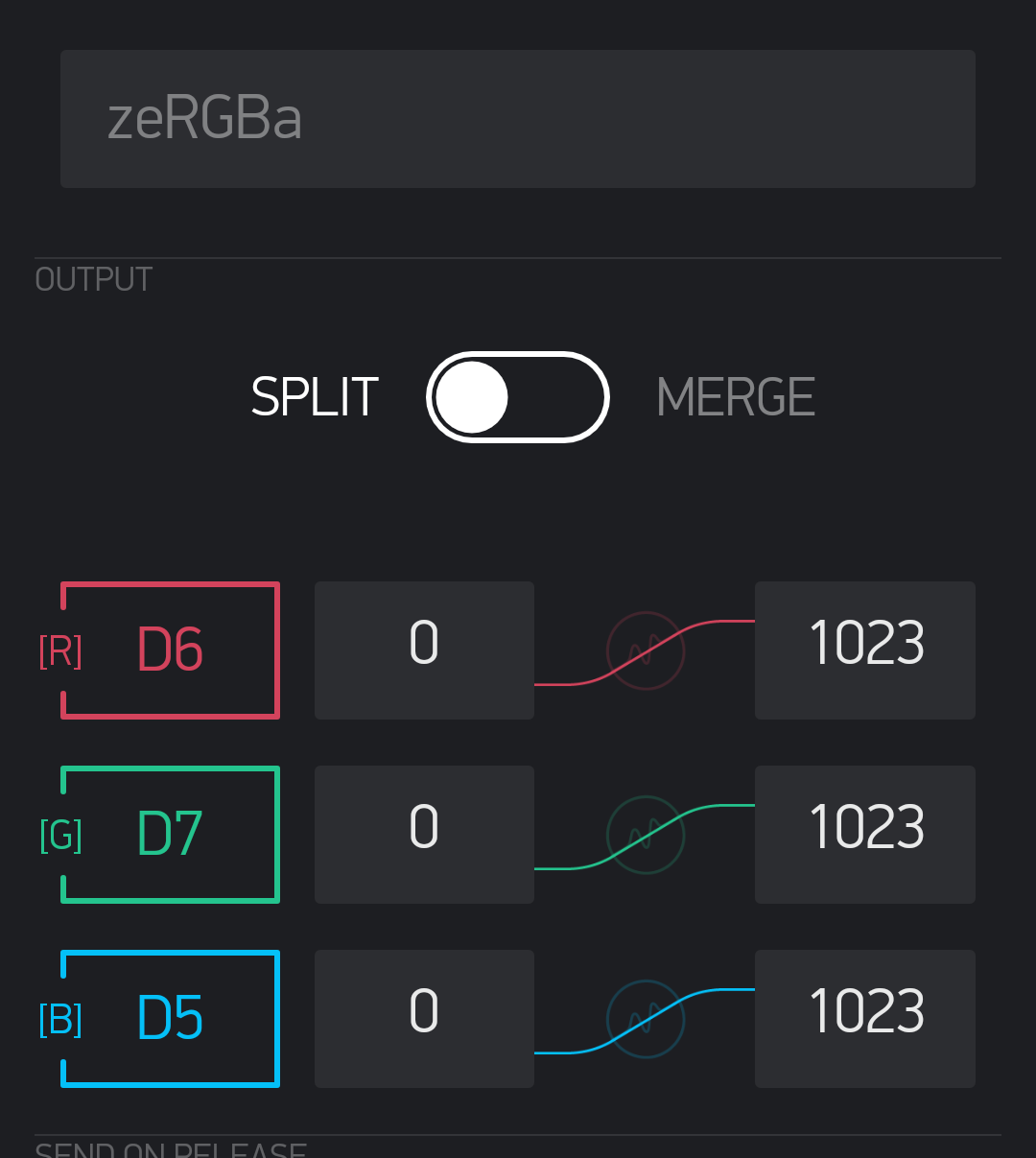
Is your code using analogWrite commands?
If so, are you writing 255 or 1023 to the GPIOs to obtain maximum brightness?
ESP8266 based boards have have a 10-bit PWM, giving 1024 brightness levels, compared to an 8-bit PWM for Arduinos. So, if you use Arduino code and write 255 as the maximum brightness to your GPIO then you’ll only be getting a 1/4 duty-cycle.
So, you’re using digital pins in the app. I’m not really sure how that works with PWM via Blynk - I guess it depends on the board type you’ve chosen in the app, and what the Blynk library does with that data once it’s received.
Personally, I’d always use virtual pins in the app and handle the RGB control using analogWrite commands in the sketch.
Tried with analogwrite function
Same result
Current drop - 0.85 A
Current I’m using BJT S8050 which is current control transistor
Should I use Mosfet ? , as it is voltage control and better for the application
Code used ;
#define BLYNK_PRINT Serial
#include <ESP8266WiFi.h>

#include <BlynkSimpleEsp8266.h>

#define R 14
#define G 12
#define B 13


char auth[] = "Jc0-5o1xduYr2aV0VQH6XLriRftx";
char ssid[] = "ssid";         // Your WiFi credentials.
char pass[] = "pass";    // Set password to "" for open networks.


BLYNK_WRITE(V1)
{
  int pinValue = param.asInt(); // assigning incoming value from pin V1 to a variable
  analogWrite(R, pinValue);

}

BLYNK_WRITE(V2)
{
  int pinValue = param.asInt(); // assigning incoming value from pin V2 to a variable
  analogWrite(G, pinValue);

}

BLYNK_WRITE(V3)
{
  int pinValue = param.asInt(); // assigning incoming value from pin V3 to a variable
  analogWrite(B, pinValue);

}

void setup()
{
  // Debug console
  Serial.begin(9600);

  WiFi.begin(ssid, pass);
  Blynk.config(auth, IPAddress(192,168,89,92), 8080);//, ssid, pass);
}

void loop()
{
  Blynk.run();
}
@Vedant please edit your post, using the pencil icon at the bottom, and add triple backticks at the beginning and end of your code so that it displays correctly.
Triple backticks look like this:
```
Though IRFZ44N it is not TTL (logic level) MOSFET , it requires around 9v to flow full current . That is not problem in my case as current is only approx 0.50 A per mosfet.

