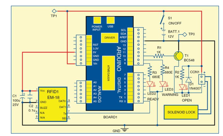
HARDWARE : uno , em18 reader ,usb
code :-
#define BLYNK_PRINT DebugSerial
#define Ready 8
#define Relay 10
#define Warning 9
char tag[] =“4A007BD4A045”; // TAG 2
char input[12];
int count = 0;
boolean match = 0;
#include <SoftwareSerial.h>
SoftwareSerial DebugSerial(2,3); // RX, TX
#include <BlynkSimpleStream.h>
char auth[] = “457ef09885034e5f90d388cf751247bd”;
WidgetLCD lcd(V5);
void setup()
{
Serial.begin(9600);
    pinMode(Ready,OUTPUT);
pinMode(Relay,OUTPUT);
pinMode(Warning,OUTPUT);
Blynk.begin(Serial, auth);
lcd.clear();
}
void loop()
{
digitalWrite(Ready,HIGH);
if(Serial.available())// check serial data ( RFID reader)
{
            digitalWrite(Ready,LOW);
	count = 0; // Reset the counter to zero
	/* Keep reading Byte by Byte from the Buffer till the RFID Reader Buffer is	empty
	   or till 12 Bytes (the ID size of our Tag) is read */
	while(Serial.available() && count < 12)
	{
		input[count] = Serial.read(); // Read 1 Byte of data and store it in the input[] variable
		count++; // increment counter

	}
	/* When the counter reaches 12 (the size of the ID) we stop and compare each value
	    of the input[] to the corresponding stored value */
	if(count == 12) //
	{
		count =0; // reset counter varibale to 0
		match = 1;
		/* Iterate through each value and compare till either the 12 values are
		   all matching or till the first mistmatch occurs */
		while(count<12 && match !=0)
		{
			if(input[count]==tag[count])
			match = 1; // everytime the values match, we set the match variable to 1
			else
			match= 0;
                           /* if the ID values don't match, set match variable to 0 and
                              stop comparing by exiting the while loop */
			count++; // increment i
		}
	}
	if(match == 1) // If match variable is 1, then it means the tags match
	{
	//	Serial.println("Congratulation Access Allowed");

 lcd.clear();
 lcd.print(4, 0, "Congratulation Access Allowed");
	}
	else
	{
		//Serial.println("Access Denied"); // Incorrect Tag Message

  lcd.clear();
  lcd.print(4, 0, "Access Denied");
	}
	/* Fill the input variable array with a fixed value 'F' to overwrite
	all values getting it	empty for the next read cycle */
	for(count=0; count<12; count++)
	{
		input[count]= 'F';
	}
	count = 0; // Reset counter variable
}
Blynk.run();
}
when i connected to the blynk app with advanced lcd (v5)
shows nothing in a output but in serial monitor it shows only auth. token again again .
i just want to print acess granted or denied in the lcd when i used the correct rfid tag .
can any one help me ???
You need to correctly format your code so that it displays correctly.
However, from what I can see you’re trying to use the same serial UART for both your Blynk USB connection and your RFID reader - which won’t work.
Pete.
Googling the RFID module that you’re using, it appears that it can be switched between a serial interface and a Wiegand protocol. If you switch to Wiegand and use a suitable library then life could be so much easier for you.
Pete.
hey pete thanks for answering but can you please elaborate actually i’m tottally noob in uno and iot .thanks in advance.
You select the Wiegand propocol rather than RS232 by pulling the SEL pin low (connecting it to ground).
You then use the D0 and D1 pins as shown in this link:
Pete.
bro sorry i’m not understand how it all work
can you edit the suitable changes in the code
this my code to acess control using tag . now can you tell how to code this so i can print the suitable values with the blynk lcd over usb connection
code—
#define Ready 8
#define Relay 10
#define Warning 9
char tag[] =“4A007BD4A045”; // Replace with your Tag ID
char input[12];
int count = 0;
boolean match = 0;
void setup()
{
Serial.begin(9600);
pinMode(Ready,OUTPUT);
pinMode(Relay,OUTPUT);
pinMode(Warning,OUTPUT);
}
void loop()
{
digitalWrite(Ready,HIGH);
if(Serial.available())// check serial data ( RFID reader)
{
digitalWrite(Ready,LOW);
count = 0; // Reset the counter to zero
/* Keep reading Byte by Byte from the Buffer till the RFID Reader Buffer is empty
or till 12 Bytes (the ID size of our Tag) is read /
while(Serial.available() && count < 12)
{
input[count] = Serial.read(); // Read 1 Byte of data and store it in the input[] variable
count++; // increment counter
delay(5);
}
/ When the counter reaches 12 (the size of the ID) we stop and compare each value
of the input[] to the corresponding stored value /
if(count == 12) //
{
count =0; // reset counter varibale to 0
match = 1;
/ Iterate through each value and compare till either the 12 values are
all matching or till the first mistmatch occurs /
while(count<12 && match !=0)
{
if(input[count]==tag[count])
match = 1; // everytime the values match, we set the match variable to 1
else
match= 0;
/ if the ID values don’t match, set match variable to 0 and
stop comparing by exiting the while loop /
count++; // increment i
}
}
if(match == 1) // If match variable is 1, then it means the tags match
{
Serial.println(“Congratulation Access Allowed”);
digitalWrite(Relay,HIGH);
delay (5000); // Relay on for 5 sec
digitalWrite (Relay,LOW);
}
else
{
Serial.println(“Access Denied”); // Incorrect Tag Message
digitalWrite(Warning,HIGH);
delay(500);
digitalWrite(Warning,LOW);
}
/ Fill the input variable array with a fixed value ‘F’ to overwrite
all values getting it empty for the next read cycle */
for(count=0; count<12; count++)
{
input[count]= ‘F’;
}
count = 0; // Reset counter variable
}
}
please help`
bro previously i’m using this connection setup for em18 and arduino
and now i connected the sel to gnd and d0 -2 pin ,d1-3pin .
and what about changes in code???
Start by going back to your first post, hitting the and “edit this post” icon at the bottom (a picture of a pencil) then inserting three backticks and cpp at the beginning of your code and three backticks at the end of your code - like this…
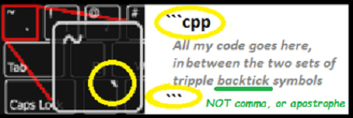
Then do the same for the next post where you inserted incorrectly formatted code.
Then follow the link I provided earlier to a Wiegand Arduino library, download and install the library (click the green “Clone or Download” button on the Github page and choose Download ZIP). Import the Zip library into your Arduino IDE (Google it if you don’t know how to do this), then flash the example code from the library to your Arduino. Test it and make sure it works, and make a note of the code that relates to your RFID tag (it may not be the same as the code you obtained by reading it a different way).
You’ll then have proven your new hardware setup works, and have the necessary library installed.
You can then set about trying to integrate the example RFID code into your Blynk sketch. If you get stuck then post your (correctly formatted) code and explain the problems that you’re experiencing and we’ll pointy you in the right direction.
Pete.