A fairly random picture:
The relay sits on top of the WeMos but are there proper headers that allow you to do this?
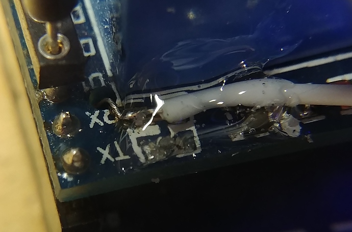
The solder on the pins of the WeMos foul the normal female headers.
Perhaps Google knows.
A fairly random picture:
The relay sits on top of the WeMos but are there proper headers that allow you to do this?
The solder on the pins of the WeMos foul the normal female headers.
Perhaps Google knows.
Google brings up stackable headers that don’t work as far as I can see:
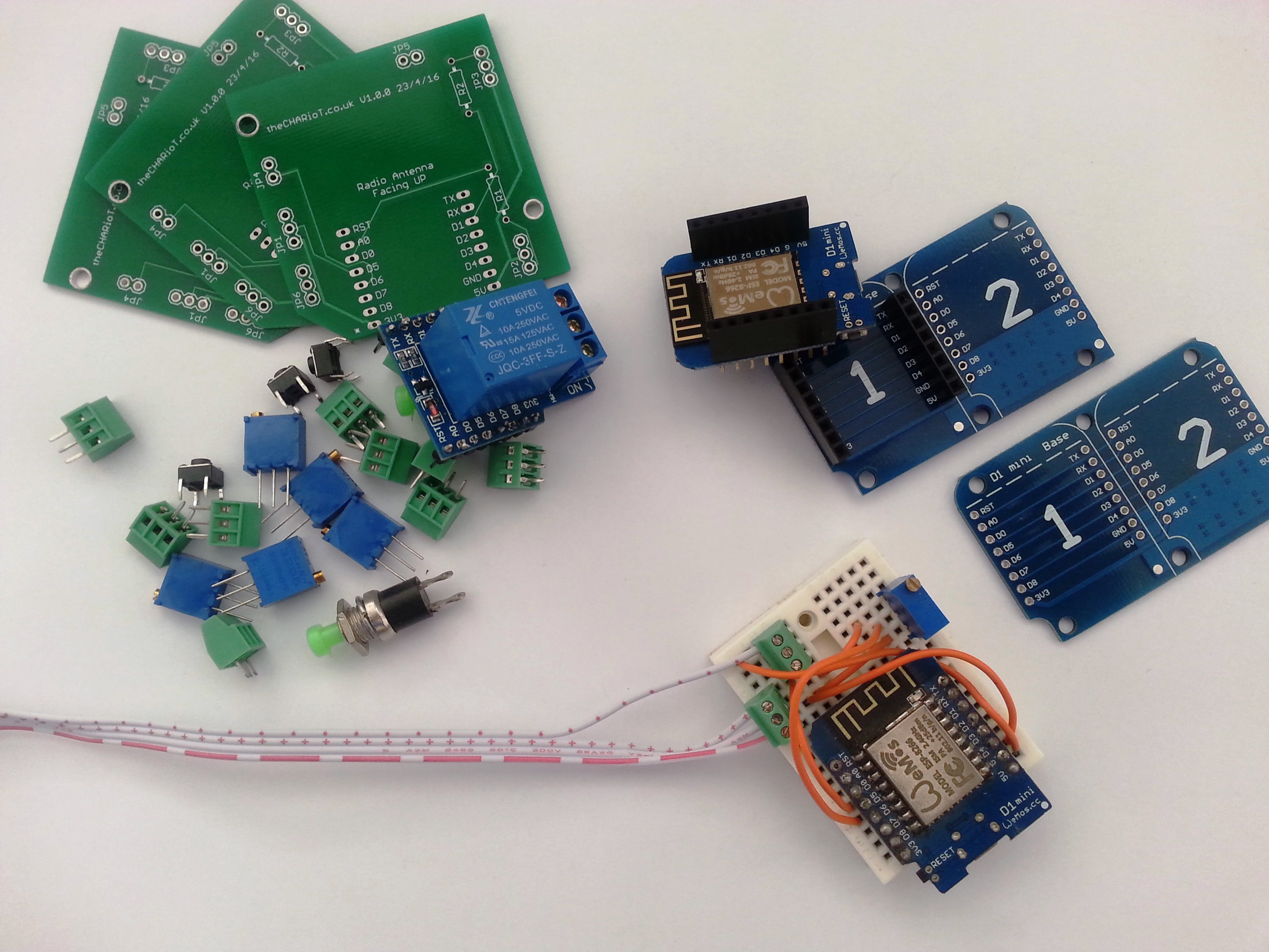
So you want to have a Wemos dual base, a Wemos then a relay stacked on top of that?
The stackable headers are what I’d use. They come with the Wemos’s that I order, along with a header that looks the same but has very short pins (the sort you solder to the dual base), plus a set of regular male pins.
When you put the stackable header pins through the Wemos you have room on the bottom to solder the pin to the board without it fouling the top of the female header soldered to the base.
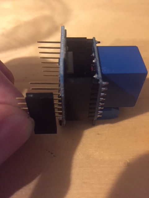
Here’s a quick photo. You can see the pins on the stackable header are fairly long, so when they’re pushed all the way into the header on the base (the bit I’m holding in my fingers) there’s still a bit sticking out (about 2.5mm), so the blob of solder on the underside of the Wemos won’t prevent it from going all the way in. These pins aren’t soldered in, as that isn’t the setup I use, but you can see that there’s enough room.
You might need to work on your soldering skills a bit though!
Pete.
Thanks guys.
I’m not really planning to use the dual boards I just put them in the photo to confuse you.
I was expecting there to be a system where all the pins are flush with the headers.
I’m hoping to go into soldering retirement any day soon ![]()
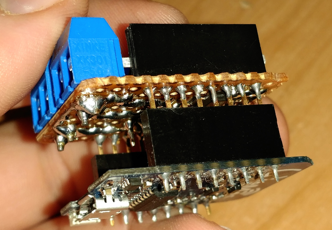
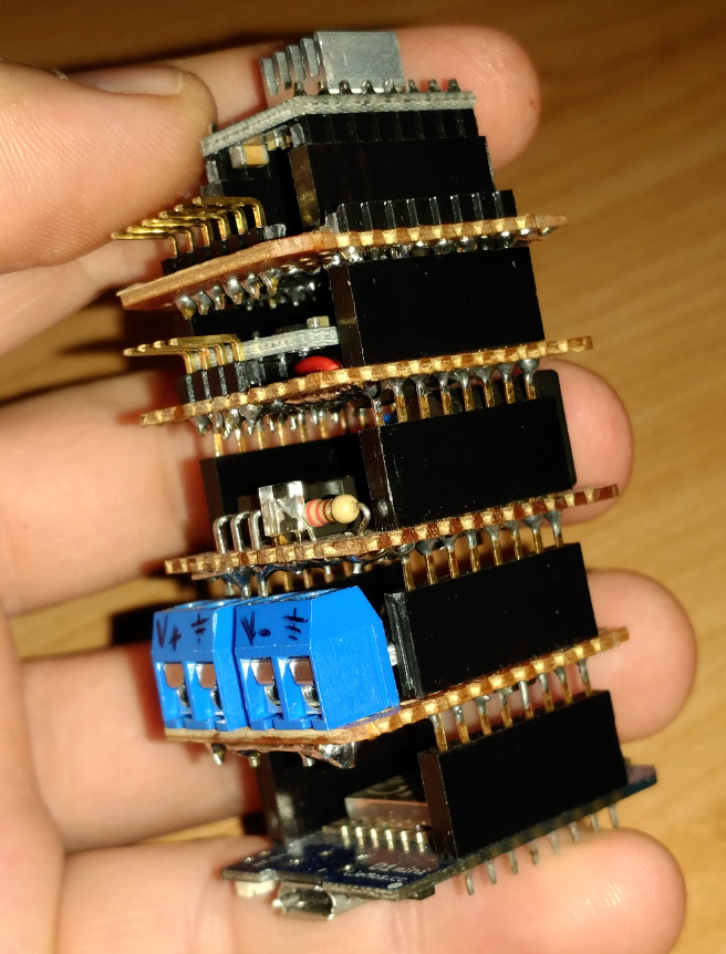
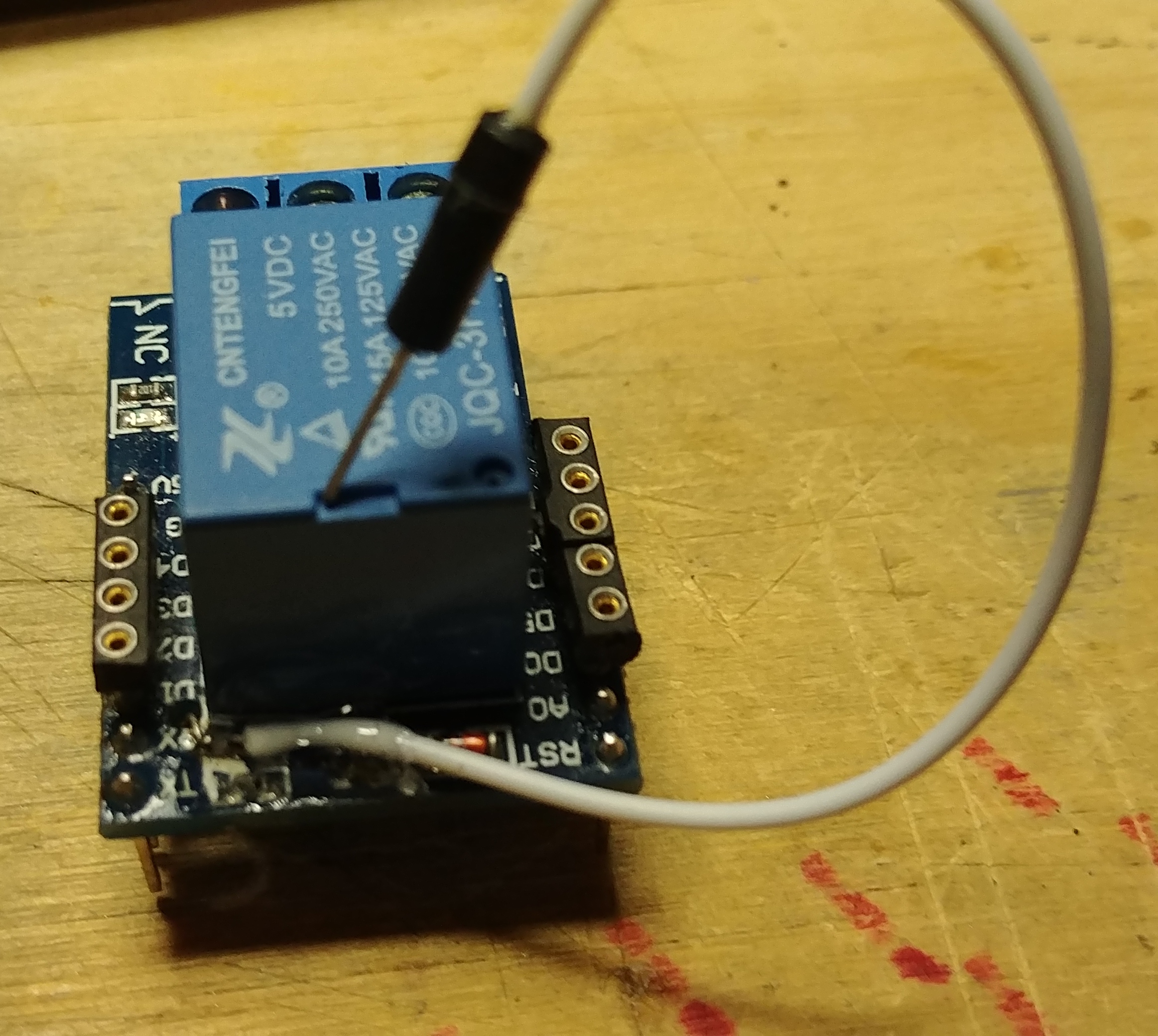
I have even gone a step further and made a stackable relay… you should try this type of soldering job @Costas 
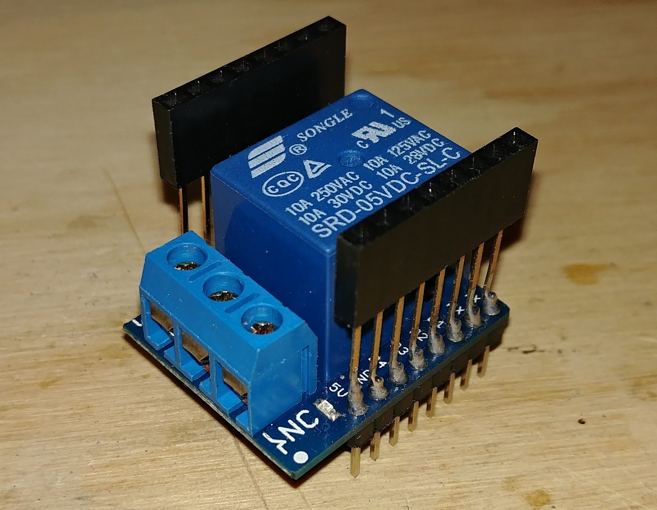
And while this one isn’t stackable, it is selectable for the data pin.
Nice work.
Could you expand on this?
A normal relay shield is hardwired for one pin (D1)… so you can’t have multiple relay shields, even if you stack or used multi bases.
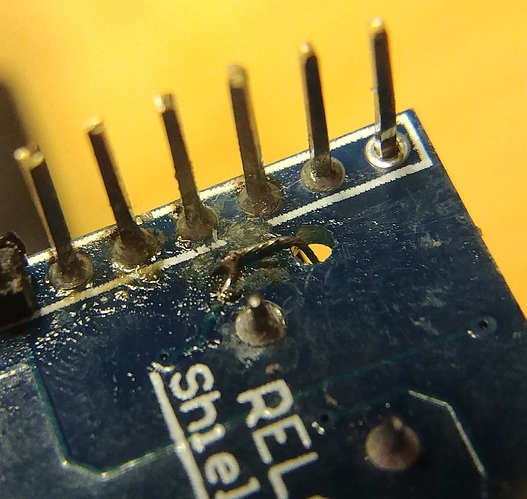
So I cut the trace to the pin and attached a lead to the trace source instead, then added in some female type headers on the pins that will work. Then I simply move the lead to the pin of choice and program for it as normal.
The shield I did this on was a clone and had multiple leads, one the to pin and one to the LED (and on opposite sides of the PCB), so it took a bit of extra drilling and patching to keep the LED working with any pin I chose.
Good hack!