and it runs smoothly to control 4 channel relay with NodemCu…but why not run on 1 channel relay because it can only on and can not off…relay 1 channel running normally when i test manual …i have same problem with 2pcs 1channel relays
video test https://twitter.com/erickfloors/status/929708946532605952
so to control 4 ch relays and 1 ch its different code?why it not work using the same code on 4ch relays? because blynk apps will be automatic control on cloud server
You should be aware that you’re not using ANY code to control your relays, as code you provided is only connecting your board to Blynk server. Direct control of GPIO pins will work, of course.
However, I think your 1-channel relay board is faulty. I had similar experience, those relay boards without optocoupling isolation are really bad, so try to avoid them.
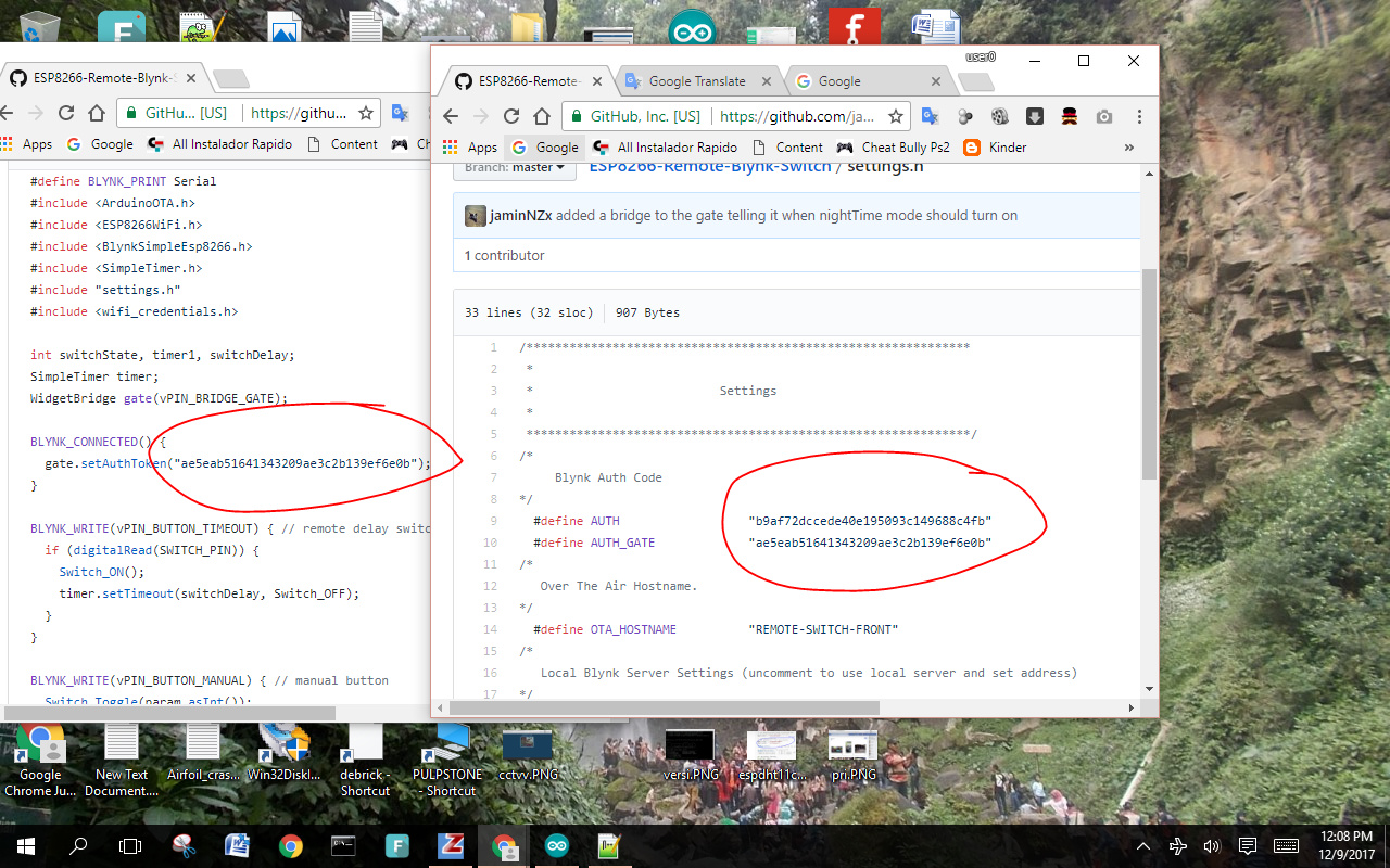
hi @Jamin why there is 2 different token on the each tab?
I always fail to use 1 channel relay, but work perfect with 4 ch relay … how to put virtual pin on 1 ch relay…
thx
There are sooo many examples of this simple use of virtual pins all over this forum. Please just do some searching and reading… you don’t even need to focus on relays, just LOOK at the code. and try it.
Set a Button Widget with virtual pin 1
Then whenever that button is pressed or released, the part of the code you did have (called a Blynk Function) will get called (runs) and the integer pinData will take on the value you have set in the widget (typically 0 or 1)
You then need to do something with that value in order that make something work… for example triggering GPIO5 (Pin 15 in Arduino) to go LOW on 0 or HIGH on 1
… Like this…
BLYNK_WRITE(V1) //Button Widget is writing to pin V1
{
  int pinData = param.asInt(); // This integer takes on the value or state of the button
  digitalWrite(15, pinData); // This command outputs the pinData value or state to a physical pin - in this case GPIO5 or Arduino pin 15
}
As for your relays working or not… not all GPIO pins are created equal… some have built in pull-up resistors, some are used for special purposes and cannot be pulled LOW when booting, all tend to use a different numbering layout on the board then is used in the Arduino code, etc.
Some relays are triggered on a LOW others on a HIGH signal
Some relays require additional pull up or pull down resistors in order to properly trigger
Some relays require the full 5v to trigger or at least more current the some ESP’s seem to produce.
All you can to is experiment…we cannot tell you exactly what will or will not work… or why. We can only guess based on what you tell us.