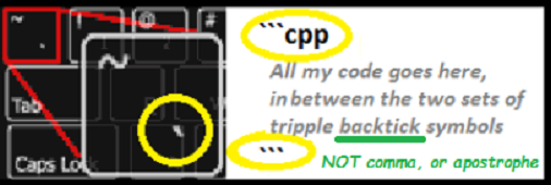
Fixed your formatting… backticks, not commas.
An ADC reads a range based on the MCU limitations… Arduino usually 0-1024 based on 0-5v, ESP8266 0-1024 based on 0-3.3v and it’s own internal voltage divider.
If you are using an ESP8266 like a NodeMCU or Wemos D1Mini, then you need to account for that internal voltage divider and adjust additional series resistance (not another divider) for the max voltage you need to monitor. Then, yes, you need to account for the algebraic equation to make 0-15v (car battery under charge - aka vehicle running) give a corresponding range from the ADC of 0-1023
I did something similar here for my 12v powered rover (battery NOT ever monitored under charge… but I calculated up to 14.8v I think).
Of course since me and Math do not get along, I think I found a formula online and fiddled with the numbers until the Blynk reading matched the multimeter reading ![]()