The code below is an attempt to read the state of a switch on pin 16 of an ESP8266-12E
It uploads OK but it fails to operate properly. Everything worked fine while I was just setting a LED and reading an analog input.
Is the approach below suitable or is there a better way?
#define BLYNK_PRINT Serial // Comment this out to disable prints and save space #include <ESP8266WiFi.h> #include <BlynkSimpleEsp8266.h>
bool current = 0;
bool previous = 1;

// You should get Auth Token in the Blynk App.
// Go to the Project Settings (nut icon).
char auth[] = "xxxxxxx";

void setup()
{
  Serial.begin(9600);
  Blynk.begin(auth, "xxxxxxx", "xxxxxxx");
  pinMode(16,INPUT_PULLUP);
}

void switchstate(){
  current = digitalRead(16);
  if (current != previous){
    previous = current;
    if (current == LOW)
          {
              Blynk.virtualWrite(3, "CLOSED");
          }
          else
         {
               Blynk.virtualWrite(3, "OPEN");
         }
  }
}

void loop()
{

  Blynk.run();
  switchstate();

}
@donold I can’t see a lot wrong with your sketch but a few things I would recommend:
It is normal practise to use Simple Timer or Ticker to time events rather than putting them in the loop. So perhaps every second call switchstate() from Simple Timer or Ticker.
I always thought virtual pins were referenced with a V but the new 32+ seem to ONLY work without the V. Might be worth trying pins 0 to 31 with a V.
Is your switch wired LOW or HIGH, is it a momentary switch?
I would avoid GPIO 16 as one day you might want to use that pin (and only that pin) for deepsleep.
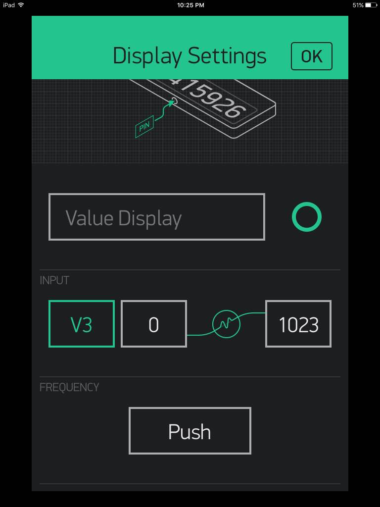
I guess my main problem is understanding how to get the indicator on Blynk to write “High” or “Low” as I expected from the code. Also when I run it I just get pulsing of my LED, The frequency part is not needed as it should only write when the switch changes state.
I think that simple timer may be better and will implement it
Will try with a V to see what happens
It is not momentary
Point taken I will change it shortly.
Do you know of any simple examples of how to read a switch state and the appropriate Blynk settings?
Take a look at Button Poll in the More, Examples of the IDE but change from Ethernet to ESP.
#define BLYNK_PRINT Serial
#include <SPI.h>
#include <Ethernet.h>
#include <BlynkSimpleEthernet.h>

// You should get Auth Token in the Blynk App.
// Go to the Project Settings (nut icon).
char auth[] = "YourAuthToken";

void setup()
{
  Serial.begin(9600);
  Blynk.begin(auth);

  // Make pin 2 default HIGH, and attach INT to our handler
  pinMode(2, INPUT_PULLUP);
}

int prevState = -1;
int currState = -1;
long lastChangeTime = 0;

void checkPin()
{
  // Invert state, since button is "Active LOW"
  int state = !digitalRead(2);

  // Debounce mechanism
  long t = millis();
  if (state != prevState) {
    lastChangeTime = t;
  }
  if (t - lastChangeTime > 50) {
    if (state != currState) {
      currState = state;
      Blynk.virtualWrite(V1, state);
    }
  }
  prevState = state;
}

void loop()
{
  Blynk.run();
  checkPin();
}
Thanks Costas your example worked.
Will tidy it up a bit and try the Simple Timer trick as it is probably a better approach.
I often find that it sometimes takes a few upload attempts before it is successful. Do others experience these problems or am I unique?
Maybe it’s because I get cheap eBay ESP8266 boards. I am waiting on delivery of a better (more expensive anyway) board.
Some upload attempts respond like this:
error: Failed to open COM3
error: espcomm_open failed
error: espcomm_upload_mem failed
It eventually uploads successfully. I never have problems with a standard Arduino Uno. The ESP8266 boards seem to be a bit hairy. I don’t think it’s my power supply but will investigate further. I have got a 2200uF cap across the supply which maybe a little under rated at only about 200mA capacity. Once successfully uploaded there are no problems.
I think many people have problems uploading to the ESP’s but when you consider the price of an ESP with and Arduino plus a shield the ESP wins hands down.
If you go for something like the WeMos D1 Mini and set the upload speed to 115200 you should get close to 100% upload success. Excellent product for $4 and no messing about with capacitors and the like.