PZEM-017 with Blynk

Hello,
I’m currently working on PZEM-017 to measure the voltage and energy usage of my solar system.

I had PZEM-017 connect to “TTL to RS485 Module” and ESP8266 D1 Mini

Here is the connection:

ESP D5 --> RS485 TxD
ESP D6 --> RS485 RxD
ESP 5V --> RS485 VCC --> PZEM017 5V
ESP G --> RS485 GND --> PZEM017 GND
RS485 A --> PZEM A
RS485 B --> PZEM B

After running the code as posted below, the serial display zezo even those there is a reading on actual device.
U_PR: 0.00
I_PR: 0.000
P_PR: 0.00
PPR: 0.000

Please help me so it can display the actual reading.

Here is the code:

#include <ArduinoOTA.h>
#include <BlynkSimpleEsp8266.h>
#include <SimpleTimer.h>
#include <ModbusMaster.h>
#include <ESP8266WiFi.h>
#include "settingsPZEM017.h"

#include <SoftwareSerial.h>  //  ( NODEMCU ESP8266 )
SoftwareSerial pzem(D5,D6);  // (RX,TX) connect to TX,RX of PZEM for NodeMCU
#include <ModbusMaster.h>
ModbusMaster node;
SimpleTimer timer;

//WiFi data
char ssid[] = "xxxxxx";                    //WiFi Credential
char pass[] = "xxxxx";              //WiFi Password
char server[] = "xxx.xxx.xxx.xxx";         //Blynk local server IP address
int port = 8080;                        //Blynk local port
#define USE_LOCAL_SERVER                //Use local Blynk Server - comment-out if use Blynk hosted cloud service
#define AUTH    "xxxxxxxxxxxxxxxxxxx"    //PZEM-017 Auth code for Blynk Local Server

int timerTask1;
double U_PR, I_PR,  P_PR,  PPR;
uint8_t result;  uint16_t data[6];


void setup(){
  Serial.begin(115200); Serial.println("Start serial"); pzem.begin(9600); Serial.println("Start PZEM serial");
node.begin(1, pzem);  Serial.println("Start PZEM"); // 1 = ID MODBUS

WiFi.mode(WIFI_STA);
#if defined(USE_LOCAL_SERVER)
  WiFi.begin(ssid, pass);
  Blynk.config(AUTH, server, port);
#else
  Blynk.begin(AUTH, ssid, pass);
#endif
  while (Blynk.connect() == false) {}
  ArduinoOTA.setHostname(OTA_HOSTNAME);
  ArduinoOTA.begin();

}

void updateBlynk() {
  Blynk.virtualWrite(vPIN_VOLTAGE,               U_PR);
  Blynk.virtualWrite(vPIN_CURRENT_USAGE,         I_PR);
  Blynk.virtualWrite(vPIN_ACTIVE_POWER,          P_PR);
  Blynk.virtualWrite(vPIN_ACTIVE_ENERGY,         PPR);

}

void loop(){
Blynk.run();

uint8_t result;                                                                                   
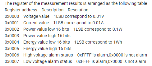
          result = node.readInputRegisters(0x0000, 6);                                                    
          if (result == node.ku8MBSuccess)                                                                
            {
              uint32_t tempdouble = 0x00000000;                                                          
              U_PR = node.getResponseBuffer(0x0000) / 100.0;                                       
                                                                                                      
              I_PR = node.getResponseBuffer(0x0001) / 100.0;                                      
              
              tempdouble =  (node.getResponseBuffer(0x0003) << 16) + node.getResponseBuffer(0x0002);      
              P_PR = tempdouble / 10.0;                                                             
              
              tempdouble =  (node.getResponseBuffer(0x0005) << 16) + node.getResponseBuffer(0x0004);      /
              PPR = tempdouble;                                                                    
            
 
            }

    Serial.print("U_PR:     "); Serial.println(U_PR);   // V
    Serial.print("I_PR:     "); Serial.println(I_PR,3);   //  A
    Serial.print("P_PR:     "); Serial.println(P_PR);   //  W 
    Serial.print("PPR:      "); Serial.println(PPR,3);   // kWh
   
Serial.println("====================================================");


updateBlynk();
  delay(1000);

Are you sure that the register addresses for the PZEM-17 are the same as the 14/16 model that this code is written for?

Also, are you sure that the RS485 to TTL adapter that you’re using is an appropriate solution?
The RS458 to TTL that I use to interrogate and control my solar charge controller has additional pins which need to be connected to GPIOs to control the direction of data flow.

Oh, and there’s the little matter of your void loop!

Pete.

Looking a bit closer, I think that these RS485 to TTL adapters that you have are sold in pairs as they are intended to be used to extend RS485 communication range by converting the signals to TTL then back again - as opposed to being designed for interfacing with MCUs.

That’s not to say that that couldn’t be used for MCU interfacing, but the “mutual conversion” part of the description sounds a bit worrying.

Pete.

HI Pete,

The register that I’m using is coming from company website for PZEM-17, below is the screenshot for it
image

What did I do wrong, did I missed anything?
Please help.

Regards,
Key

Those addresses appear to be the same as the ones you are using, which in your original code sais “read the 9 registers (information) of the PZEM-014 / 016”, which is why I queried it.

Are you getting anything back from your PZEM-017 which might prove your RS485 to TTL is working?

Pete.

When using PZEM17 with the USB cable through the computer, yes, I do get the reading from it.

When connect to RS485 and the code above, all I get is:

  • U_PR: 0.00
    I_PR: 0.000
    P_PR: 0.00
    PPR: 0.000

Hi Pete,

Would you please help me on fixing this reading issue on PZEM17.

Do you have a different RS485 to TTL adapter yet?

Pete.

Hi Pete,

Yes, I do have another RS485 adapter and already replaced it but the reading still show zero.

could it be something missing on the code or may be the connection as I don’t see it?

Regards,
Key

What type of adapter do you have?

Pete.

i’m using this:

image

link here “TTL to RS485 Module

That’s the same one as in your original post.

Pete.

corrected, it’s the same type. I had 3 available and I replaced it (I though the board may be bad) all but still only show the zero readout.

As I’ve said, I think that these are designed for long range comms and they seem to be self-negotiating with regard to baud rate. I don’t see how that could be compatible with what you are tying to achieve.

I may be wrong, but don’t have either of your pieces of hardware available to do any testing if my own.
The boards seem to have Tx and Rx LEDs on them. Which seem to be on the RS485 side. Is there any activity on these?

Pete.

Yes, the board does have Tx and Rx LED on it but I don’t see any activity when it run.

Could it be because I have wrong connection?
ESP D5 --> RS485 TxD
ESP D6 --> RS485 RxD
ESP 5V --> RS485 VCC --> PZEM017 5V
ESP G --> RS485 GND --> PZEM017 GND
RS485 A --> PZEM A
RS485 B --> PZEM B

I have no idea, I’m not familiar with this adapter, but I doubt that it is suitable for this application.

Pete.

Found this Image For your adapter. Maybe it will help, maybe not.

To be honest I do not have much experience with this, but maybe try using the actual GPIO numbers instead of the “D” numbers.

SoftwareSerial pzem(D5,D6);  // (RX,TX) connect to TX,RX of PZEM for NodeMCU
SoftwareSerial pzem(14,12);  // (RX,TX) connect to TX,RX of PZEM for NodeMCU

Thanks Toro,

I have been using this same type of board for my other project like EPEVER Solar charge controller and it’s working fine.

There could be some code missing or wrong code which I can’t see or detect it as i’m “blind” now.

Can any of you look into the code to see if you can find anything wrong with it?

Sharing that piece of information, and the code you Re using, earlier in the discussion would have saved several of us a significant amount of time.

Pete.