 You don’t… that was just a Plain English retelling of an existing example meant to assist in learning basic principles… replace “elapsed time since boot” with “something else” like running a pump or blinking a light, or…or…or…
Maybe I will stick to excel and basic vba… I keep looking, reading, wondering, day dreaming that it will come together but I have been staring at a brick wall.
I need a book “arduino for the dummiest dummies.”
You will get there with practice… I learn best by doing (aka… fail, fail, fail, oh… I get it now… fail ![]() ) Then and only then can I begin to understand the manual
) Then and only then can I begin to understand the manual ![]() Two years ago, when I started with Arduino and Blynk, I couldn’t even understand how to install IDE libraries… and I have been a computer tech most of my working life
Two years ago, when I started with Arduino and Blynk, I couldn’t even understand how to install IDE libraries… and I have been a computer tech most of my working life ![]()
I hear you, in reality I know I would get there eventually, like every other skill I’ve picked up along the way.
I just simply won’t get there due to the lack of time I have available, certainly not for this Christmas anyway which was my intention!
@Amsok, your plain English explanation is exactly what you need. It is interpreting that into code where it becomes tricky. I will try to assist as best I can.
For this part, I would use THIS as a starting point. So take the time to go through it and understand it. It is a way to sync a physical button, with a virtual button in the app, while activating a digital pin (set D8 High/Low). This would be how you start/stop the misting cycle. In that example, you would want to merge the code you have written above so that you can pass the times for the cycle (i.e timers).
Once you get there repost your merged code, and I will try to assist further.
Thanks Toro, Gunner
How does this look, to grab the button state from the app.
Don’t shoot me!
#define BLYNK_PRINT Serial
#include <ESP8266WiFi.h>
#include <BlynkSimpleEsp8266.h>

float MistRunTime;
int DelayTime;
const int btnPin = 7; //The start button will be assigned to D7 INPUT via app
int btnState = HIGH; //Shouldn't this be LOW to begin with?

BlynkTimer timer;

// You should get Auth Token in the Blynk App.
// Go to the Project Settings (nut icon).
char auth[] = "";

// Your WiFi credentials.
// Set password to "" for open networks.
char ssid[] = "";
char pass[] = "";


void checkPhysicalButton()  //assume this function checks for the button state and locks it in to V7
{
  if (digitalRead(btnPin) == LOW) {
    // btnState is used to avoid sequential toggles
    if (btnState != LOW) {

      // Update Button Widget
      Blynk.virtualWrite(V7, btnState); //I assume this will lock in to V7 the state of the button from the app HIGH or LOW
    }
    btnState = LOW;
  } else {
    btnState = HIGH;
  }
}


BLYNK_WRITE (V1) // Time interval for misting 0.5-10 seconds
{
MistRunTime = param.asFloat(); // assigning incoming value from pin V1 to a variable

Serial.println(MistRunTime);
}


BLYNK_WRITE (V2) // Time interval for delay 5-120 seconds
{
DelayTime = param.asInt(); // assigning incoming value from pin V2 to a variable

Serial.println(DelayTime);
}


void setup()
{
  // Debug console
  Serial.begin(9600);

  Blynk.begin(auth, ssid, pass);
  // You can also specify server:
  //Blynk.begin(auth, ssid, pass, "blynk-cloud.com", 80);
  //Blynk.begin(auth, ssid, pass, IPAddress(192,168,1,100), 8080);

  // Setup a function to be called every 100 ms
  timer.setInterval(100L, checkPhysicalButton);
  //assume this is what makes the function happen - every 100ms?
  //why the L in this case? without the L would still be 100ms?
}


void loop()
{
  Blynk.run();
  timer.run();
}
For some reason, you left a bunch of stuff out from the example. You will need all of that.
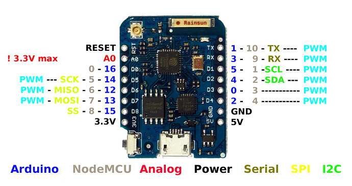
Also, you want to use the GPIO pins, not the D values written on the board. There are also certain pins you should stay away from on the ESP Modules (unless you know what you are doing). D8 (GPIO15) is one of them.
/* Comment this out to disable prints and save space */
#define BLYNK_PRINT Serial


#include <ESP8266WiFi.h>
#include <BlynkSimpleEsp8266.h>

// You should get Auth Token in the Blynk App.
// Go to the Project Settings (nut icon).
char auth[] = "YourAuthToken";

// Your WiFi credentials.
// Set password to "" for open networks.
char ssid[] = "YourNetworkName";
char pass[] = "YourPassword";

// Set your LED and physical button pins here
const int ledPin = 12; //GPIO pin relay is attached to (D6)
const int btnPin = 13; //pin physical button is attached to. wired between GPIO13 (D7) and GND

BlynkTimer timer;
void checkPhysicalButton();

int ledState = LOW; //assuming active HIGH relay, change to LOW if active LOW
int btnState = HIGH;

// Every time we connect to the cloud...
BLYNK_CONNECTED() {
  // Request the latest state from the server
  Blynk.syncVirtual(V1, V2, V7);

}

// When App button is pushed - switch the state. The button should be on virtual pin 7 and set to switch
BLYNK_WRITE(V7) {
  ledState = param.asInt();
  digitalWrite(ledPin, ledState);
}

void checkPhysicalButton()
{
  if (digitalRead(btnPin) == LOW) {
    // btnState is used to avoid sequential toggles
    if (btnState != LOW) {

      // Toggle LED state
      ledState = !ledState;
      digitalWrite(ledPin, ledState);

      // Update Button Widget
      Blynk.virtualWrite(V7, ledState);
    }
    btnState = LOW;
  } else {
    btnState = HIGH;
  }
}

BLYNK_WRITE (V1) // Time interval for misting 0.5-10 seconds
{
MistRunTime = param.asFloat(); // assigning incoming value from pin V1 to a variable

Serial.println(MistRunTime);
}


BLYNK_WRITE (V2) // Time interval for delay 5-120 seconds
{
DelayTime = param.asInt(); // assigning incoming value from pin V2 to a variable

Serial.println(DelayTime);
}

void setup()
{
  // Debug console
  Serial.begin(9600);

  Blynk.begin(auth, ssid, pass);
  // You can also specify server:
  //Blynk.begin(auth, ssid, pass, "blynk-cloud.com", 80);
  //Blynk.begin(auth, ssid, pass, IPAddress(192,168,1,100), 8080);

  pinMode(ledPin, OUTPUT);
  pinMode(btnPin, INPUT_PULLUP);
  digitalWrite(ledPin, ledState);

  // Setup a function to be called every 100 ms
  timer.setInterval(100L, checkPhysicalButton);
}

void loop()
{
  Blynk.run();
  timer.run();
}
From here, we will need to do some slight modifications, and add some timers to get the functionality you need.
I left the LED state bit out thinking I won’t add an LED to the board - have I misinterpreted that function? Just trying to understand the logic.
Also how do I reference the GPIO pin instead of digital pin in the programming? I don’t think I have yet seen GPIO in any code.
You will need to add some timers and routines for the cycling. You will need an ON and OFF routing that to be called with timers.
int timerId1;
int timerId2;
void onRelay()
{
digitalWrite(ledPin, HIGH); //turn relay ON
timerId1 = timer.setTimeout(MistRunTime*1000, offRelay); //run after
}

void offRelay()
{
digitalWrite(ledPin, LOW);//turn relay OFF
timerId2 = timer.setTimeout(DelayTime*1000, onRelay); //run after
}
Now you just need to work on the physical/virtual button logic to start and stop the timers when the button is on or off.
Thanks Toro
Very much appreciate your help. I still don’t understand why “LED” is used.
I understand the rest of that code, I will try and collate it all and return post here
BTW I am using this https://alselectro.files.wordpress.com/2017/10/nodemcu_pins1.jpg
It is just a name, could just as easily be called relayPin.
Use the values listed as GPIO
Am I any closer with this?
Changed all LED to Relay so it makes sense to me
#define BLYNK_PRINT Serial
#include <ESP8266WiFi.h>
#include <BlynkSimpleEsp8266.h>

float MistRunTime;
int DelayTime;
int RelayState = LOW; //assuming active HIGH relay, change to LOW if active LOW
int btnState = HIGH;
int timerId1;
int timerId2;

// Set your Relay and physical button pins here
const int RelayPin = 1;
const int btnPin = 2;

BlynkTimer timer;

// You should get Auth Token in the Blynk App.
// Go to the Project Settings (nut icon).
char auth[] = "";

// Your WiFi credentials.
// Set password to "" for open networks.
char ssid[] = "";
char pass[] = "";


// Every time we connect to the cloud...
BLYNK_CONNECTED() {
  // Request the latest state from the server
  Blynk.syncVirtual(V2);

  // Alternatively, you could override server state using:
  //Blynk.virtualWrite(V2, RelayState);
}

// When App button is pushed - switch the state
BLYNK_WRITE(V2) {
  RelayState = param.asInt();
  digitalWrite(RelayPin, RelayState);
}

void checkPhysicalButton()
{
  if (digitalRead(btnPin) == LOW) {
    // btnState is used to avoid sequential toggles
    if (btnState != LOW) {

      // Toggle Relay state
      RelayState = !RelayState;
      digitalWrite(RelayPin, RelayState);

      // Update Button Widget
      Blynk.virtualWrite(V2, RelayState);
    }
    btnState = LOW;
  } else {
    btnState = HIGH;
  }
}


BLYNK_WRITE (V3) // Time interval for misting 0.5-10 seconds
{
MistRunTime = param.asFloat(); // assigning incoming value from pin V1 to a variable

Serial.println(MistRunTime);
}


BLYNK_WRITE (V4) // Time interval for delay 5-120 seconds
{
DelayTime = param.asInt(); // assigning incoming value from pin V2 to a variable

Serial.println(DelayTime);
}


void onRelay()
{
digitalWrite(RelayPin, HIGH); //turn relay ON
timer.deleteTimer(timerId1);
timerId1 = timer.setTimeout(MistRunTime*1000, offRelay); //run after
}

void offRelay()
{
digitalWrite(RelayPin, LOW);//turn relay OFF
timer.deleteTimer(timerId2);
timerId2 = timer.setTimeout(DelayTime*1000, onRelay); //run after
}


void loop()
{
  Blynk.run();
  timer.run();
}
Close, take a better look at the code I posted. I would add the syncs for the other virtual pins. Also, your relay and button pins will not work. Take a look at the diagram you posted. Use the GPIO numbers listed. I would stick with pins 4, 5, 12, 13 or 14. You are also missing the void setup() function.
And you can do away with the timer.deleteTimer(timerId1); and timer.deleteTimer(timerId2);, as after some further reading they are not needed. They are automatically deleted after they run.
Appreciate it, will have a crack at this later today and post back.
Sounds good. I will be off in about an hour but will return tomorrow to see how things are going.
The next step will be getting the logic worked out. The way I would do it is to use some if () and else if () statements along with a “flag” to determine when the onRelay and offRelay routines should be running. I would check the flag in the onRelay routine, and if it is not set then don’t run.
And just so you know, I am mostly doing this out of my own self-interest. I need something very similar for a project I am working on that includes an adjustable, cycling relay. So it seems your timing was just right.
Ok here’s the latest, if I need to bang my head against the wall let me know!
#define BLYNK_PRINT Serial
#include <ESP8266WiFi.h>
#include <BlynkSimpleEsp8266.h>

float MistRunTime;
int DelayTime;
int RelayState = LOW; //assuming active HIGH relay, change to LOW if active LOW
int btnState = HIGH;
int timerId1;
int timerId2;

// Set your Relay and physical button pins here
const int RelayPin = 4;
const int btnPin = 5;

BlynkTimer timer;

// You should get Auth Token in the Blynk App.
// Go to the Project Settings (nut icon).
char auth[] = "";

// Your WiFi credentials.
// Set password to "" for open networks.
char ssid[] = "";
char pass[] = "";


// Every time we connect to the cloud...
BLYNK_CONNECTED() {
  // Request the latest state from the server
  Blynk.syncVirtual(V2);
  Blynk.syncVirtual(V3);
  Blynk.syncVirtual(V4);

  // Alternatively, you could override server state using:
  //Blynk.virtualWrite(V2, RelayState);
}

// When App button is pushed - switch the state
BLYNK_WRITE(V2) {
  RelayState = param.asInt();
  digitalWrite(RelayPin, RelayState);
}

void checkPhysicalButton()
{
  if (digitalRead(btnPin) == LOW) {
    // btnState is used to avoid sequential toggles
    if (btnState != LOW) {

      // Toggle Relay state
      RelayState = !RelayState;
      digitalWrite(RelayPin, RelayState);

      // Update Button Widget
      Blynk.virtualWrite(V2, RelayState);
    }
    btnState = LOW;
  } else {
    btnState = HIGH;
  }
}


BLYNK_WRITE (V3) // Time interval for misting 0.5-10 seconds
{
MistRunTime = param.asFloat(); // assigning incoming value from pin V1 to a variable

Serial.println(MistRunTime);
}


BLYNK_WRITE (V4) // Time interval for delay 5-120 seconds
{
DelayTime = param.asInt(); // assigning incoming value from pin V2 to a variable

Serial.println(DelayTime);
}


void onRelay()
{
digitalWrite(RelayPin, HIGH); //turn relay ON
timerId1 = timer.setTimeout(MistRunTime*1000, offRelay); //run after
}

void offRelay()
{
digitalWrite(RelayPin, LOW);//turn relay OFF
timerId2 = timer.setTimeout(DelayTime*1000, onRelay); //run after
}


void setup()
{
  // Debug console
  Serial.begin(9600);

  Blynk.begin(auth, ssid, pass);
  // You can also specify server:
  //Blynk.begin(auth, ssid, pass, "blynk-cloud.com", 80);
  //Blynk.begin(auth, ssid, pass, IPAddress(192,168,1,100), 8080);

  pinMode(RelayState, OUTPUT);
  pinMode(btnPin, INPUT_PULLUP);
  digitalWrite(RelayState, RelayState);

  // Setup a function to be called every 100 ms
  timer.setInterval(100L, checkPhysicalButton);

if (btnState=HIGH)
{
onRelay();
}
else if (btnState=LOW)
{
offRelay();
}
}


void loop()
{
  Blynk.run();
  timer.run();
}
Unless I am too sleepy to understand ![]() … once you start this process, it will never end, as each one refers back to the other without any form of cancelation option.
… once you start this process, it will never end, as each one refers back to the other without any form of cancelation option.
EDIT - although since you have assigned each timer an ID, you can add in some other function that can disable both as needed with these commands
timer.disable(timerId1);
timer.disable(timerId2);
Hi Gunner,
Do you mean like this?
if (btnState=HIGH)
{
onRelay();
}
else if (btnState=LOW)
{
timer.disable(timerId1);
timer.disable(timerId2);
}