Hi, I have been working on a project. It controls most parts of my aquarium. It has a solenoid valve, pump and 4 float sensors and 1 flood sensor. On the Blynk I have 4 buttons. The 1st button turns on the solenoid valve to drain the aquarium. 2nd button turns on the pump which puts new water in the tank. The 3rd button is automatic mode. It drains the some of the water with the use of the solenoid and then fills new water from another bucket. The flood sensors control how much of the tank needs to be drained and filled. 2 of the sensors
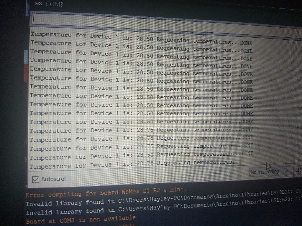
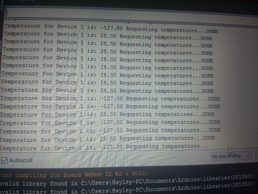
are placed in the bucket with the pump so that the pump stops when the bucket is empty and another sensor to prevent the drain bucket from being over filled. The other 2 are placed where the tank is topped off and the other one below it and it is used to drain to that point. After I finished the code the project kept disconnecting and connecting instantly sometimes when a button is pressed. Even when the Esp turns on in the app it says connected , disconnects and then reconnects again. This all happens within a second. This morning the pump was turned on and I am sure it was off the day before. I have no idea how it magically turned no. Also I have a DS18B20 temp sensor that constantly displays -127 and then the actual Temp. Maybe this is causing the disconnects?? I am so confused:disappointed_relieved: . It`s quite a big sketch. Ignore void turn_on that just turns the lights on. I am using a Wemos D1 Mini Pro. If you need pictures just ask.
Thanks in Advance
#include <ArduinoOTA.h>
#define BLYNK_PRINT Serial    // Comment this out to disable prints and save space
#include <ESP8266WiFi.h>
#include <BlynkSimpleEsp8266.h>
#include <Wire.h>
#include "Adafruit_MCP23008.h"
#include <TimeLib.h>
#include <WidgetRTC.h>

#include <OneWire.h>
#include <DallasTemperature.h>
OneWire oneWire (14); //esp
DallasTemperature sensors(&oneWire);

WidgetLCD lcd(V13);

WidgetRTC rtc;

Adafruit_MCP23008 mcp;

#define white 13 //esp
#define fan 12 //esp

#define SUNRISE 9*60 + 0
#define DAWN 10*60 + 0
#define DUSK 16*60 + 0
#define SUNSET 17*60 + 0

#define drain_bucket_full 4 //mcp
#define fill_bucket_empty 6 //mcp
#define aquarium_empty 5 //mcp
#define aquarium_full 1 //mcp

#define Fill_Pump 2 //mcp
#define solenoid 0 //mcp

#define watersensor 3

int sensor = 0;

WidgetLED Pump(V2);
WidgetLED Solenoid_valve(V7);
WidgetLED Done(V8);
WidgetLED Auto(V9);
WidgetLED error(V10);

WidgetLED fanled(V12);
WidgetLED whiteled(V11);

BlynkTimer timer;

boolean emergencystop = 0;

int timer1;
int timer2;
int timer3;
boolean start = 0;

int var;
int state;

char auth[] = "5xxxxxxxxxxxxxxxxxxxxxxxxxxxx1a2";
char ssid[] = "Claxxxxxxxxxxxxxxxxxxxxx-Fi";
char pass[] = "claxxxxxxxxxxxxx3";


BLYNK_WRITE(V0) // At global scope (not inside of the function)

{
  if ( param.asInt() == 1 )
  {
    timer.enable(timer1);
  } else {
    timer.disable(timer1);
    state = 0;
    Done.off();
    var = 4;
    lcd.clear();
  }
}

BLYNK_WRITE(V1) // At global scope (not inside of the function)
{
  if ( param.asInt() == 1 )
  {
    timer.enable(timer2);
  } else {
    timer.disable(timer2);
    state = 0;
    var = 2;
    Done.off();
    lcd.clear();
  }
}

BLYNK_WRITE(V5) // At global scope (not inside of the function)

{
  if ( param.asInt() == 1 )
  {
    timer.enable(timer3);
  }
  else
  {
    timer.disable(timer3);
    Auto.off();
    Done.off();
    var = 5;
    lcd.clear(); //Use it to clear the LCD Widget
    state = 0;

  }
}

BLYNK_WRITE(V6) // Stop Button

{
  if ( param.asInt() == 1 )
  {
    var = 5;
    lcd.clear():

    }
  }

  BLYNK_WRITE(V14) //Debug Purposes

{
  if ( param.asInt() == 1 )
  {
    Blynk.virtualWrite(V15, var);
    Blynk.virtualWrite(V16, state);
  }
}

void water_sensor () {

  if (mcp.digitalRead(watersensor) == 1) {
    error.off();

  }
  else
  {
    var = 5;
    lcd.print(0, 0, "Water on the    "); // use: (position X: 0-15, position Y: 0-1, "Message you want to print")
    lcd.print(0, 1, "floor          ");
    error.on();
    mcp.digitalWrite(Fill_Pump, LOW);
    Pump.off();
    mcp.digitalWrite(solenoid, LOW);
    Solenoid_valve.off();
    Done.off();
    Auto.off();

  }
}
void solenoid_on() {
  mcp.digitalWrite(solenoid, HIGH);
  Solenoid_valve.on();
}

void solenoid_off() {
  mcp.digitalWrite(solenoid, LOW);
  Solenoid_valve.off();
}
void Pump_on() {
  mcp.digitalWrite(Fill_Pump, HIGH);
  Pump.on();
}
void Pump_off() {
  mcp.digitalWrite(Fill_Pump, LOW);
  Pump.off();
}

void all_off() {
  mcp.digitalWrite(Fill_Pump, LOW);
  Pump.off();
  mcp.digitalWrite(solenoid, LOW);
  Solenoid_valve.off();
  Done.off();
  Auto.off();
}


void fill() {
  if (state == 0 && sensor == 0 && mcp.digitalRead(fill_bucket_empty) == HIGH && mcp.digitalRead(aquarium_full) == LOW)
  {
    var = 3;
    lcd.print(0, 0, "Filling with   "); // use: (position X: 0-15, position Y: 0-1, "Message you want to print")
    lcd.print(0, 1, "Water          ");
    state = 1;

  }

  if (state == 1 && mcp.digitalRead(fill_bucket_empty) == LOW) {
    lcd.print(0, 0, "Filling Bucket "); // use: (position X: 0-15, position Y: 0-1, "Message you want to print")
    lcd.print(0, 1, "is Empty       ");
    state = 0;
    var = 4;
  }


  if (state == 1 && mcp.digitalRead(aquarium_full) == HIGH)
  {
    var = 4;
    state = 3;
    lcd.print(0, 0, "Change Done     "); // use: (position X: 0-15, position Y: 0-1, "Message you want to print")
    lcd.print(0, 1, "               ");
    Done.on();
  }


}


//---------------------------------------------------------------------------------------------------------------------

void drain() {

  //Drain
  if (state == 0 && mcp.digitalRead(drain_bucket_full) == LOW && mcp.digitalRead(aquarium_empty) == HIGH) {
    var = 1;
    lcd.print(0, 0, "Draining mode "); // use: (position X: 0-15, position Y: 0-1, "Message you want to print")
    lcd.print(0, 1, "Draining Water");
    state = 1;

  }

  if (state == 1 && mcp.digitalRead(drain_bucket_full) == HIGH) {

    lcd.print(0, 0, "Drain Bucket is"); // use: (position X: 0-15, position Y: 0-1, "Message you want to print")
    lcd.print(0, 1, "Full           ");
    var = 2;
    state = 0;
  }

  if (state == 1 && mcp.digitalRead(aquarium_empty) == LOW) {
    lcd.print(0, 0, "Water Drained   "); // use: (position X: 0-15, position Y: 0-1, "Message you want to print")
    lcd.print(0, 1, "               ");
    var = 2;
    state = 3;
    Done.on();
  }
}
//------------------------------------------------------------------------------------------------------------------------


void turn_on() { //light control
  int value = 0;
  int msm = hour() * 60 + minute(); //minutes since midnight

  if ( msm < SUNRISE ) {
    value = 0;
  } else if (msm < DAWN) {
    value = map(msm, SUNRISE, DAWN, 0, 1024);
  } else if (msm < DUSK ) {
    value = 1024;
  } else if (msm < SUNSET ) {
    value = map(msm, DUSK, SUNSET, 1024, 0);
  } else {
    value = 0;
  }

  int brightness = map(value, 0, 1024, 0, 255);

  whiteled.setValue(brightness);


  //BLYNK_LOG("Time: %d %d - setting lights to %d", hour(), minute(), value);

  analogWrite(white, value);

}

void temp() {
  sensors.requestTemperatures();
  float currentTemp;
  currentTemp = sensors.getTempCByIndex(0);
  Blynk.virtualWrite(V4, currentTemp); // Virtual 0


  if (currentTemp >= 28.5) {
    analogWrite(fan, 1024);
    fanled.on();
  }
  else if (currentTemp <= 28.5)
  {
    analogWrite(fan, 0);
    fanled.off();
  }

}

void setup() {
  WiFi.mode(WIFI_STA);
  Serial.begin(9600);
  mcp.begin();      // use default address 0
  // Start up the library

  Blynk.begin(auth, ssid, pass);

  while (Blynk.connect() == false) {}
  sensors.begin();
  // sensors.setResolution(10);
  ArduinoOTA.setHostname("Aquarium"); // OPTIONAL
  ArduinoOTA.begin();

  pinMode(white, OUTPUT);
  pinMode(fan, OUTPUT);

  mcp.pinMode(drain_bucket_full, INPUT);
  mcp.pinMode(fill_bucket_empty, INPUT);
  mcp.pinMode(aquarium_empty, INPUT);
  mcp.pinMode(watersensor, INPUT);
  mcp.pinMode(aquarium_full, INPUT);

  mcp.pullUp(drain_bucket_full, HIGH);  // turn on a 100K pullup internally
  mcp.pullUp(fill_bucket_empty, HIGH);
  mcp.pullUp(aquarium_empty, HIGH);
  mcp.pullUp(aquarium_full, HIGH);

  mcp.pinMode(Fill_Pump, OUTPUT);
  mcp.pinMode(solenoid, OUTPUT);

  mcp.digitalWrite(Fill_Pump, LOW);
  mcp.digitalWrite(solenoid, LOW);
  lcd.clear();

  // Begin synchronizing time
  rtc.begin();

  timer.setInterval(10000L, turn_on);
  //timer.setInterval(1000L, clockDisplay);
  timer.setInterval(2000L, temp);
  timer.setInterval(1000L, water_sensor);
  timer1 = timer.setInterval(500L, fill);
  timer2 = timer.setInterval(500L, drain);
  timer3 = timer.setInterval(1500L, auto_mode);
  timer.disable(timer1);
  timer.disable(timer2);
  timer.disable(timer3);
}

void loop() {

  switch (var) {
    case 1: solenoid_on();
      break;
    case 2: solenoid_off();
      break;
    case 3: Pump_on();
      solenoid_off();
      break;
    case 4: Pump_off();
      break;
    case 5: all_off();
      break;

    default:
      // if nothing else matches, do the default
      // default is optional
      break;
  }

  Blynk.run();
  ArduinoOTA.handle();
  timer.run();
}