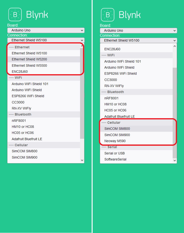
Greetings to all the Blynk community I hope you can help me with my problem, so that you have context of my situation regarding the project I am developing is a device based on an ESP32 WROOM-32D, an ethernet chip ENC28J60 and a SIMCom A7672SA module. The idea is that the device is connected by ethernet cable to the Blynk platform to control alternating loads (a clarification regarding the project, this was developed because the condition is that it works by ethernet cable and not by Wi-Fi). So far so good, it connects to the platform and you can take measurements and interact with the loads, the problem arises when I want to compile the code for the device to switch between connecting via ethernet cable or mobile data (GSM communication) because the idea is that if there is no internet via Ethernet cable should be connected to the Blynk platform by mobile data (GSM communication) through the SIMCom A7672SA module, but when compiling the project the program gives me a conflict in the Blynk library of Arduino with the following libraries:
//#define _SIM_CLARO_
//#define _SIM_TIGO_
#define _SIM_MOVISTAR_
/* Comment this out to disable prints and save space */
#define BLYNK_PRINT Serial
/* Fill-in your Template ID (only if using Blynk.Cloud) */
#define BLYNK_TEMPLATE_ID "YourTemplateID"
#define BLYNK_DEVICE_NAME "Control AC"
#define BLYNK_AUTH_TOKEN "YourToken"
// Select your modem:
#define TINY_GSM_MODEM_BG96
// Default heartbeat interval for GSM is 60
// If you want override this value, uncomment and set this option:
#define BLYNK_HEARTBEAT 30
#include <UIPEthernet.h>
#include <BlynkSimpleUIPEthernet.h>
#include <TinyGsmClient.h>
#include <BlynkSimpleTinyGSM.h>
#include <Wire.h> // Incluimos la libreria para el protocolo I2C.
#include <SPI.h> // Incluimos la libreria para el protocolo SPI.
#ifdef _SIM_CLARO_
// https://selectra.com.co/empresas/claro/apn
#define APN_SIM "internet.comcel.com.co"
#define USER_SIM "comcel"
#define PASS_SIM "comcel"
#endif
#ifdef _SIM_TIGO_
// https://selectra.com.co/empresas/tigo/apn
#define APN_SIM "colombiamovil.com.co"
#define USER_SIM ""
#define PASS_SIM ""
#endif
#ifdef _SIM_MOVISTAR_
// https://selectra.com.co/empresas/movistar/apn
#define APN_SIM "internet.movistar.com.co"
#define USER_SIM "movistar"
#define PASS_SIM "movistar"
#endif
// You should get Auth Token in the Blynk App.
// Go to the Project Settings (nut icon).
char auth[] = BLYNK_AUTH_TOKEN;
// Your GPRS credentials
// Leave empty, if missing user or pass
char apn[] = APN_SIM;
char user[] = USER_SIM;
char pass[] = PASS_SIM;
#define STATE_POWER 14 // Pin GPIO14 leer estado de alimentacion.
#define PIN_CH1 2 // Pin GPIO15 leer estado de alimentacion.
#define PIN_CH2 15 // Pin GPIO02 enciende el led de la placa.
#define PWRKEY_SIMCOM 12 // Pin GPIO04_ADC2_0 como pin digital que activa el POWER del modulo SIMCOM para que comience a funcionar.
#define ESP32_RXD2 16 // Pin GPIO16_RXD2 como pin digital que se conecta con el TX del modulo SIMCOM para recibir las respuestas de los comandos AT.
#define ESP32_TXD2 17 // Pin GPIO17_TXD2 como pin digital que se conecta con el RX del modulo SIMCOM para enviar los comandos AT.
#define SPI_SS 5 // Pin GPIO05_SPI_SS como pin digital que se conecta con el chip ENC28J60/SS para realizar una conexion LAN por SPI.
#define SPI_SCK 18 // Pin GPIO18_SPI_SCK como pin digital que se conecta con el chip ENC28J60/SS para realizar una conexion LAN por SPI.
#define SPI_MISO 19 // Pin GPIO19_SPI_MISO como pin digital que se conecta con el chip ENC28J60/SS para realizar una conexion LAN por SPI.
#define I2C_SDA 21 // Pin GPIO21_I2C_SDA como pin digital que se conecta con el chip PCF8575TS para expandir los pines y controlarlo por comunicacion I2C.
// PINES RESERVADOS PARA LA COMUNICACION SERIAL PRINCIPAL:
#define ESP32_RXD0 3 // Pin GPIO03_RXD0 como pin digital que se conecta con el TX del FT232 para recibir informacion por serial desde el PC.
#define ESP32_TXD0 1 // Pin GPIO01_TXD0 como pin digital que se conecta con el RX del FT232 para enviar informacion por serial al PC.
#define I2C_SCL 22 // Pin GPIO22_I2C_SCL como pin digital que se conecta con el chip PCF8575TS para expandir los pines y controlarlo por comunicacion I2C.
#define SPI_MOSI 23 // Pin GPIO23_SPI_MOSI como pin digital que se conecta con el chip ENC28J60/SS para realizar una conexion LAN por SPI.
#define ADC_READ 34 // Pin GPIO34 como pin digital que se conecta con el chip ENC28J60/SS para realizar una conexion LAN por SPI.
//********************************************* Variables Macros **************************************************
#define BAUDRATE_UART0 115200 // Define la velocidad de transmision serial.
#define BAUDRATE_UART1 9600 // Define la velocidad del transferencia del ESP32 en el UART1.
#define BAUDRATE_UART2 115200 // Define la velocidad del transferencia del ESP32 en el UART2.
#define UART1 1 // Numero de UART a configurar.
#define RESOLUTION_MIN 0.0 // Constante para definir la escala a la que se realizará la conversión del ADC.
#define RESOLUTION_MAX 4095.0 // Constante para definir la escala a la que se realizará la conversión del ADC.
#define VOLTAJEMIN 0.0 // Constante de voltaje para realizar los calculos del ADC.
#define VOLTAJEMAX 3.30 // Constante de voltaje para realizar los calculos del ADC.
#define CHANNEL_1 V0 // Pin virtual por donde se comunica el CANAL 1.
#define CHANNEL_2 V1 // Pin virtual por donde se comunica el CANAL 2.
#define CHANNEL_3 V2 // Pin virtual por donde se comunica el CANAL 3.
#define CHANNEL_4 V3 // Pin virtual por donde se comunica el CANAL 4.
#define BLYNK_HIGH 1 // Indicador de estado del pin.
#define BLYNK_LOW 0 // Indicador de estado del pin.
bool valorPIN = 0;
int sensorValueRaw = 0; // Variable que almacena el valor raw (0 a 4095)
float outputValue = 0; // value output to the PWM (analog out)
TinyGsm modem( Serial2 ); // Crea un objeto modem para comunicarse por el serial 2 y enviar los datos por SIMCARD.
// This function creates the timer object. It's part of Blynk library
BlynkTimer timer;
void setup() {
Serial.begin ( BAUDRATE_UART0 ); // Inicializa la comunicación serie con el PC y establecemos velocidad.
Serial2.begin ( BAUDRATE_UART2, SERIAL_8N1, ESP32_RXD2, ESP32_TXD2 ); // Inicializa la comunicación serie con el modulo SIMCom, establecemos velocidad y los pines por donde se van a comunicar.
Wire.begin(); // Inicializa la comunicación por I2C.
pinMode( PIN_CH1 , OUTPUT ); // Configura el pin GPIO04_ADC2_0 como salida digital que activa el POWER del modulo SIMCOM para que comience a funcionar.
pinMode( PIN_CH2 , OUTPUT ); // Configura el pin GPIO04_ADC2_0 como salida digital que activa el POWER del modulo SIMCOM para que comience a funcionar.
pinMode( STATE_POWER, INPUT );
pinMode( PWRKEY_SIMCOM , OUTPUT ); // Configura el pin GPIO04_ADC2_0 como salida digital que activa el POWER del modulo SIMCOM para que comience a funcionar.
pinMode( SPI_SS , OUTPUT ); // Configura el pin GPIO05_SPI_SS como salida digital que se conecta con el chip ENC28J60/SS para realizar una conexion LAN por SPI.
digitalWrite( PIN_CH1, HIGH ); // Pin digital utilizado para encender o apagar el modulo SIMCOM.
digitalWrite( PIN_CH2, HIGH ); // Pin digital utilizado para encender o apagar el modulo SIMCOM.
powerSIMCom();
changeConnection();
if ( !Blynk.connected() ) { // Si el cliente no esta conectado entonces...
Serial.println("Entro al reset");
ESP.restart();
}
// Setting interval to send data to Blynk Cloud to 1000ms.
// It means that data will be sent every second
timer.setInterval(1000L, myTimer);
}
void loop() {
if ( !Blynk.connected() && valorPIN == LOW ) { // Si el cliente no esta conectado entonces...
Serial.println("Entro al reset");
ESP.restart();
}
readPin();
measureVoltage();
Blynk.run(); // Runs all Blynk stuff
timer.run(); // runs BlynkTimer
}
void myTimer() {
// This function describes what will happen with each timer tick
// e.g. writing sensor value to datastream V5
Blynk.virtualWrite( CHANNEL_2, outputValue ); // Metodo que se encarga de enviar las medidas al pin virtual de Blynk.
Blynk.virtualWrite( CHANNEL_3, valorPIN ); // Metodo que se encarga de enviar las medidas al pin virtual de Blynk.
}
BLYNK_CONNECTED() {
// Request Blynk server to re-send latest values for all pins
Blynk.syncAll();
// You can also update individual virtual pins like this:
Blynk.syncVirtual( CHANNEL_1, CHANNEL_2, CHANNEL_3, CHANNEL_4);
}
BLYNK_WRITE( CHANNEL_1 ) { // Executes when the value of virtual pin 0 changes
if ( param.asInt() == 1 ) {
// execute this code if the switch widget is now ON
digitalWrite( PIN_CH1, HIGH ); // Pin digital utilizado para activar las salidas alternas por medio de optoacopladores CHANNEL 1.
Blynk.virtualWrite( CHANNEL_1, BLYNK_HIGH ); // Turn the widget attached to V0 ON.
}
else {
// execute this code if the switch widget is now OFF
digitalWrite( PIN_CH1, LOW ); // Pin digital utilizado para activar las salidas alternas por medio de optoacopladores CHANNEL 1.
Blynk.virtualWrite( CHANNEL_1, BLYNK_LOW ); // Turn the widget attached to V0 OFF.
}
}
BLYNK_WRITE( CHANNEL_4 ) { // Executes when the value of virtual pin 0 changes
if ( param.asInt() == 1 ) {
// execute this code if the switch widget is now ON
digitalWrite( PIN_CH2, HIGH ); // Pin digital utilizado para activar las salidas alternas por medio de optoacopladores CHANNEL 1.
Blynk.virtualWrite( CHANNEL_4, BLYNK_HIGH ); // Turn the widget attached to V0 ON.
}
else {
// execute this code if the switch widget is now OFF
digitalWrite( PIN_CH2, LOW ); // Pin digital utilizado para activar las salidas alternas por medio de optoacopladores CHANNEL 1.
Blynk.virtualWrite( CHANNEL_4, BLYNK_LOW ); // Turn the widget attached to V0 OFF.
}
}
// cambio de escala entre floats
float fmap(float x, float in_min, float in_max, float out_min, float out_max) {
return ( (x - in_min) * (out_max - out_min) / (in_max - in_min) + out_min );
}
float median( float newVal ) { //
static float buf[3]; //
static byte count = 0; //
buf[count] = newVal; //
if (++count >= 3) count = 0; //
float a = buf[0]; //
float b = buf[1]; //
float c = buf[2]; //
float middle; //
if ((a <= b) && (a <= c)) { //
middle = (b <= c) ? b : c; //
} else { //
if ((b <= a) && (b <= c)) { //
middle = (a <= c) ? a : c; //
} else { //
middle = (a <= b) ? a : b; //
} //
}
return middle; //
}
void measureVoltage() {
static unsigned long lastMillis_readPinModAC = 0; // Almacena el tiempo que transcurre en una vez se inicia el ESP32, al ser static NO se reinicia al salir de la función.
if ( ((millis() - lastMillis_readPinModAC) > 1000) ) { // Condición para delay NO bloqueante entra cada 1 segundo.
lastMillis_readPinModAC = millis(); // Almacena el valor de tiempo transcurrido en la variable para cálcular el tiempo del delay NO bloqueante.
// read the analog in value:
sensorValueRaw = median( analogRead( ADC_READ ) );
// map it to the range of the analog out:
outputValue = fmap( sensorValueRaw, RESOLUTION_MIN, RESOLUTION_MAX, VOLTAJEMIN, VOLTAJEMAX ); // cambiar escala a 0.0 - 25.0
// print the results to the Serial Monitor:
Serial.print("sensor RAW = ");
Serial.print(sensorValueRaw);
Serial.print("\t output = ");
Serial.println(outputValue);
}
}
void changeConnection() {
valorPIN = digitalRead( STATE_POWER );
if ( valorPIN == HIGH ) {
Serial.println("Initializing ethernet...");
Blynk.begin(auth);
// You can also specify server:
//Blynk.begin(auth, "blynk-cloud.com", 80);
//Blynk.begin(auth, IPAddress(192,168,1,100), 8080);
} else {
// Restart takes quite some time
// To skip it, call init() instead of restart()
Serial.println("Initializing modem...");
modem.restart();
// Unlock your SIM card with a PIN
//modem.simUnlock("1234");
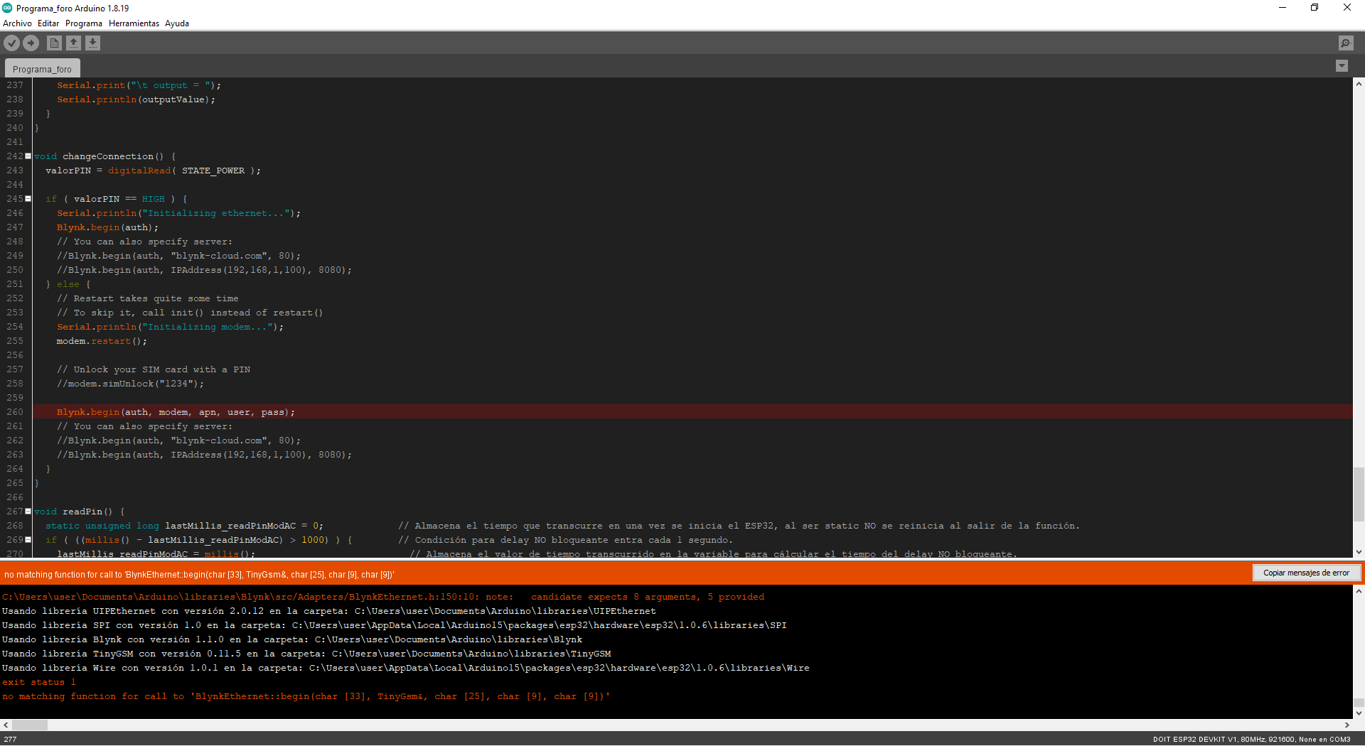
Blynk.begin(auth, modem, apn, user, pass);
// You can also specify server:
//Blynk.begin(auth, "blynk-cloud.com", 80);
//Blynk.begin(auth, IPAddress(192,168,1,100), 8080);
}
}
void readPin() {
static unsigned long lastMillis_readPinModAC = 0; // Almacena el tiempo que transcurre en una vez se inicia el ESP32, al ser static NO se reinicia al salir de la función.
if ( ((millis() - lastMillis_readPinModAC) > 1000) ) { // Condición para delay NO bloqueante entra cada 1 segundo.
lastMillis_readPinModAC = millis(); // Almacena el valor de tiempo transcurrido en la variable para cálcular el tiempo del delay NO bloqueante.
valorPIN = digitalRead( STATE_POWER );
Serial.print("Valor del PIN STATE_POWER:");
Serial.println( valorPIN );
}
}
void powerSIMCom() {
digitalWrite( PWRKEY_SIMCOM, LOW ); // Pin digital utilizado para encender o apagar el modulo SIMCOM.
delay(100); // Tiempo de espera para enviar el pulso en BAJO.
digitalWrite( PWRKEY_SIMCOM, HIGH ); // Pin digital utilizado para encender o apagar el modulo SIMCOM.
delay(1000); // Tiempo de espera para enviar el pulso en ALTO.
digitalWrite( PWRKEY_SIMCOM, LOW ); // Pin digital utilizado para encender o apagar el modulo SIMCOM.
}
Does anyone know of a method to use the two communications (Ethernet and GSM) within the same Arduino program (sketch), as much as possible without the need to use more additional hardware?
Thanks in advance to anyone who can help me.