Problem with Blink Timers 2.0 Please help

ESP8266 + Blink. Everything before the update was working fine after it I can’t get the on and off timers to work. Each button includes an output and each timer also includes the output from the button. Please help me how to insert code in the sketch to make the timers work. I have three accounts with purchased gadgets and now I want to deal with these timers to buy several subscriptions, if I can’t manage I will look for an alternative.
Code

#define BLYNK_DEVICE_NAME "77777"
#define BLYNK_AUTH_TOKEN "77777777"

#define BLYNK_PRINT Serial

#include <ESP8266WiFi.h>
#include <BlynkSimpleEsp8266.h>

char auth[] = BLYNK_AUTH_TOKEN;

char ssid[] = "ehesler";  // type your wifi name
char pass[] =  "ehesler123";  // type your wifi password
BLYNK_WRITE(V0)
{
  int value = param.asInt();
  Serial.println(value);
  if(value == 1)
  {
    digitalWrite(D1, LOW);
    Serial.println("LED ON");
  }
  if(value == 0)
  {
     digitalWrite(D1, HIGH);
     Serial.println("LED OFF");
  }
}
BLYNK_WRITE(V1)
{
  int value = param.asInt();
  Serial.println(value);
  if(value == 1)
  {
    digitalWrite(D2, LOW);
    Serial.println("LED ON");
  }
  if(value == 0)
  {
     digitalWrite(D2, HIGH);
     Serial.println("LED OFF");
  }
}
BLYNK_WRITE(V2)
{
  int value = param.asInt();
  Serial.println(value);
  if(value == 1)
  {
    digitalWrite(D3, LOW);
    Serial.println("LED ON");
  }
  if(value == 0)
  {
     digitalWrite(D3, HIGH);
     Serial.println("LED OFF");
  }
}
BLYNK_WRITE(V3)
{
  int value = param.asInt();
  Serial.println(value);
  if(value == 1)
  {
    digitalWrite(D4, LOW);
    Serial.println("LED ON");
  }
  if(value == 0)
  {
     digitalWrite(D4, HIGH);
     Serial.println("LED OFF");
  }
}
BLYNK_WRITE(V4)
{
  int value = param.asInt();
  Serial.println(value);
  if(value == 1)
  {
    digitalWrite(D5, LOW);
    Serial.println("LED ON");
  }
  if(value == 0)
  {
     digitalWrite(D5, HIGH);
     Serial.println("LED OFF");
  }
}
BLYNK_WRITE(V5)
{
  int value = param.asInt();
  Serial.println(value);
  if(value == 1)
  {
    digitalWrite(D6, LOW);
    Serial.println("LED ON");
  }
  if(value == 0)
  {
     digitalWrite(D6, HIGH);
     Serial.println("LED OFF");
  }
}
BLYNK_WRITE(V6)
{
  int value = param.asInt();
  Serial.println(value);
  if(value == 1)
  {
    digitalWrite(D7, LOW);
    Serial.println("LED ON");
  }
  if(value == 0)
  {
     digitalWrite(D7, HIGH);
     Serial.println("LED OFF");
  }
}
BLYNK_WRITE(V7)
{
  int value = param.asInt();
  Serial.println(value);
  if(value == 1)
  {
    digitalWrite(D8, LOW);
    Serial.println("LED ON");
  }
  if(value == 0)
  {
     digitalWrite(D8, HIGH);
     Serial.println("LED OFF");
  }
}
BLYNK_WRITE(V8)
{
  int value = param.asInt();
  Serial.println(value);
  if(value == 1)
  {
    digitalWrite(D9, LOW);
    Serial.println("LED ON");
  }
  if(value == 0)
  {
     digitalWrite(D9, HIGH);
     Serial.println("LED OFF");
  }
}


void setup()
{
  Serial.begin(115200);
  Blynk.begin(auth, ssid, pass);
  pinMode(D1,OUTPUT);
  pinMode(D2,OUTPUT);
  pinMode(D3,OUTPUT);
  pinMode(D4,OUTPUT);
  pinMode(D5,OUTPUT);
  pinMode(D6,OUTPUT);
  pinMode(D7,OUTPUT);
  pinMode(D8,OUTPUT);
 
}

void loop()
{
  Blynk.run();
}

Uploading: 0-02-05-9f009396d3b4322af8d01fa498e07c2a01222c7b993f60211fac7d742efe8872_2fad1b0066224d47.png…

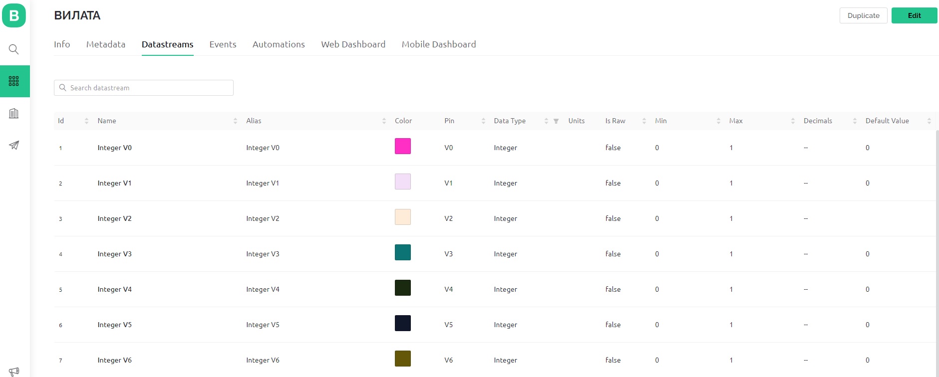
It would help if you would indicate which virtual datastreams these buttons are attached to.

It would also help if you explained more about these timers you are referring to.
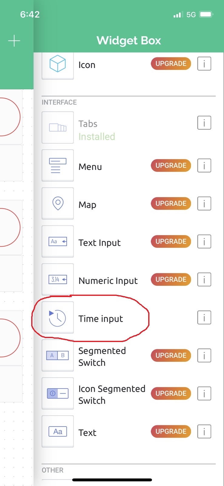
Are you talking about Timer widgets, Time Input widgets, Automations, BlynkTimers or something else?

Are you talking about Blynk Legacy accounts with purchases energy? If so then these are now inactive.

Pete.

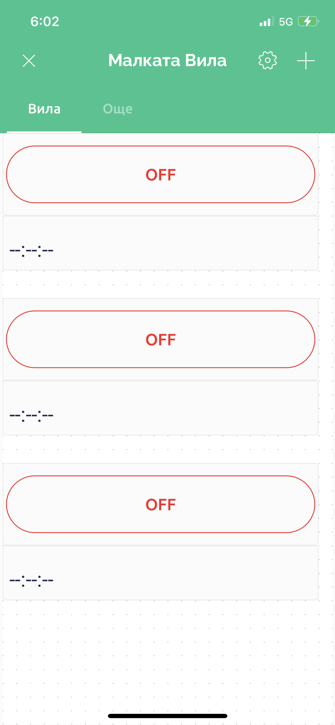
Button1 activates output integerV1 as a Switch, Timer1 under the button also activates V1 by assigning it part of start and part of stop. All other buttons and timers work the same way.Help me what to add in the code and in Datastream. This system consists of turning on several lamps at night and stopping when it becomes light, coupled with buttons for manual switching on. Therefore, there is a button for manual switching and a timer for automatic.

Uploading: t1.jpg…

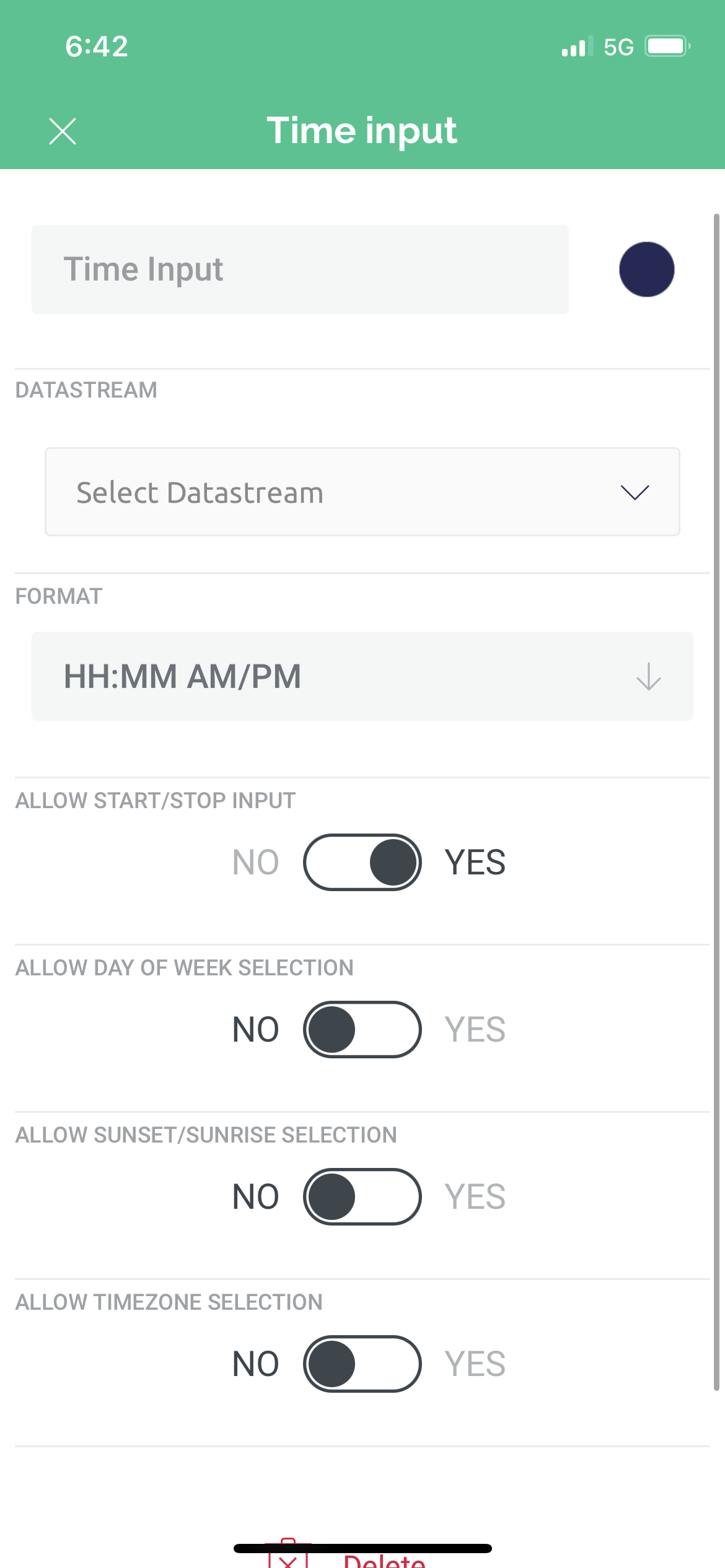
Time input widgets need to be attached to virtual datastreams with string data types, and you need to have code within your sketch which will accept the incoming start and end times (which are in seconds since midnight) and compare this to the current time evaluate whether the device should be on or off.
This is the same as using this widget in Blynk Legacy.

I suspect that you’ve previously used the Timer widget in Blynk Legacy. This isn’t available in Blynk IoT, it has been replaced with Automations.

Pete.

Please help me what should I add in the code of esp8266 and how to make changes to the Automations ?

It’s a one or the other choice, either you switch to using Automations or you create a handler for the Time Input widget data in your sketch.

If you go for the latter then thee are some examples in the forum if you d9 some searching.

Pete.

I searched but couldn’t find a way to refactor my code. Please add the necessary in the code I have uploaded.

I’m not going to re-write your sketch for you.

Pete.

It is not correct of you to close accounts of users who bought widgets and release a new version that you want users to pay monthly fees to use. How can I subscribe to your services if there is no necessary assistance from you in case of a problem? This way you will lose thousands of customers, I don’t want you to write the code for me but help me what should I add in the code and in automation so that I can use your app and subscribe.

@PeteKnight is a user just like you. He does not work for BLYNK. The discontinuation of BLYNK legacy was announced a LONG time ago and multiple times. Discounts were given for users of the old BLYNK.

Search this forum for examples. Rephrase your questions more specifically to what you are struggling with in regards to your coding. Show what you have tried, and explain what it is doing. We are here to help, not do all the work.

This seems like a request to write code, but that could just be a misunderstanding.

1 Like

Button1 activates output integerV1 as a Switch.I want to add in the sketch and in the automation a timer to control the output integerV1. To be able to tell it from the application at what time to turn on and off the output V1.
I have three lamps that I want to turn on with buttons from the application and that a timer is attached to each button to turn on and off at a set time all three outputs of esp8266

You can use automation, which is the easiest way.
https://docs.blynk.io/en/concepts/automations

As @Toro_Blanco has said, I’m nothing to do with Blunk. I’m a Blynk user and community forum member like you, and also one of the moderators of this community forum.

I’m not gpoing to…

for you, you need to do that yourself. I’ve already outlined that you have two potential options:

  1. Time Input widget and code in your sketch to handle the data that comes from this widget

or

  1. Automations.

It’s not…

it’s one OR the other.

Pete.