Here is the Code which i Uploaded to the Nodemcu. Got it from a post in Blynk Community just changed the Auth & wifi Credentials.
#define BLYNK_PRINT Serial


#include <ESP8266WiFi.h>
#include <BlynkSimpleEsp8266.h>

// You should get Auth Token in the Blynk App.
// Go to the Project Settings (nut icon).
char auth[] = "xxxxxxxxxx";

// Your WiFi credentials.
// Set password to "" for open networks.
char ssid[] = "xxxx";
char pass[] = "xxxxxxx";

// Set your LED and physical button pins here
const int ledPin1 = 12;
const int ledPin2 = 13;
const int ledPin3 = 14;
const int ledPin4 = 15;
const int btnPin1 = 5;
const int btnPin2 = 4;
const int btnPin3 = 9;
const int btnPin4 = 1;

BlynkTimer timer;
void checkPhysicalButton();

int led1State = LOW;
int btn1State = HIGH;

int led2State = LOW;
int btn2State = HIGH;

int led3State = LOW;
int btn3State = HIGH;

int led4State = LOW;
int btn4State = HIGH;

// Every time we connect to the cloud...
BLYNK_CONNECTED() {
  // Request the latest state from the server
  Blynk.syncVirtual(V12);
  Blynk.syncVirtual(V13);
  Blynk.syncVirtual(V14);
  Blynk.syncVirtual(V15);

  // Alternatively, you could override server state using:
  //Blynk.virtualWrite(V12, led1State);
  //Blynk.virtualWrite(V13, led2State);
  //Blynk.virtualWrite(V14, led3State);
  //Blynk.virtualWrite(V15, led4State);

}

// When App button is pushed - switch the state
BLYNK_WRITE(V12) {
  led1State = param.asInt();
  digitalWrite(ledPin1, led1State);
}

 BLYNK_WRITE(V13) {
  led2State = param.asInt();
  digitalWrite(ledPin2, led2State);
 }
BLYNK_WRITE(V14) {
  led3State = param.asInt();
  digitalWrite(ledPin3, led3State);
}
BLYNK_WRITE(V15) {
  led4State = param.asInt();
  digitalWrite(ledPin4, led4State);
}

void checkPhysicalButton()
{
  if (digitalRead(btnPin1) == LOW) {
    // btn1State is used to avoid sequential toggles
    if (btn1State != LOW) {

      // Toggle LED state
      led1State = !led1State;
      digitalWrite(ledPin1, led1State);

      // Update Button Widget
      Blynk.virtualWrite(V12, led1State);
    }
    btn1State = LOW;
  } else {
    btn1State = HIGH;
  }

  if (digitalRead(btnPin2) == LOW) {
    // btnState is used to avoid sequential toggles
    if (btn2State != LOW) {

      // Toggle LED state
      led2State = !led2State;
      digitalWrite(ledPin2, led2State);

      // Update Button Widget
      Blynk.virtualWrite(V13, led2State);
    }
    btn2State = LOW;
  } else {
    btn2State = HIGH;
  }

  if (digitalRead(btnPin3) == LOW) {
    // btnState is used to avoid sequential toggles
    if (btn3State != LOW) {

      // Toggle LED state
      led3State = !led3State;
      digitalWrite(ledPin3, led3State);

      // Update Button Widget
      Blynk.virtualWrite(V14, led3State);
    }
    btn3State = LOW;
  } else {
    btn3State = HIGH;
  }

  if (digitalRead(btnPin4) == LOW) {
    // btnState is used to avoid sequential toggles
    if (btn4State != LOW) {

      // Toggle LED state
      led4State = !led4State;
      digitalWrite(ledPin4, led4State);

      // Update Button Widget
      Blynk.virtualWrite(V15, led4State);
    }
    btn4State = LOW;
  } else {
    btn4State = HIGH;
  }
}

void setup()
{
  // Debug console
  Serial.begin(9600);

  Blynk.begin(auth, ssid, pass);
  // You can also specify server:
  //Blynk.begin(auth, ssid, pass, "blynk-cloud.com", 8442);
  //Blynk.begin(auth, ssid, pass, IPAddress(192,168,1,100), 8442);

  pinMode(ledPin1, OUTPUT);
  pinMode(btnPin1, INPUT_PULLUP);
  digitalWrite(ledPin1, led1State);


  pinMode(ledPin2, OUTPUT);
  pinMode(btnPin2, INPUT_PULLUP);
  digitalWrite(ledPin2, led2State);


  pinMode(ledPin3, OUTPUT);
  pinMode(btnPin3, INPUT_PULLUP);
  digitalWrite(ledPin3, led3State);


  pinMode(ledPin4, OUTPUT);
  pinMode(btnPin4, INPUT_PULLUP);
  digitalWrite(ledPin4, led4State);

  // Setup a function to be called every 100 ms
  timer.setInterval(500L, checkPhysicalButton);
}

void loop()
{
  Blynk.run();
  timer.run();
}
After this connected the Relays to D5 / GPIO14, D6 / GPIO12, D7 / 13, D8 / 15.
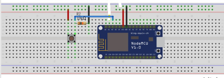
then connected the Physical push buttons to the following pins - D1 / GPIO5 , D2 / GPIO4 , SD1 / GPIO10, SD2 / GPIO9 using a 10kohm resistor connected to ground and gave the other pin of button to 3.3v ( both taken form nodemcu itself).
the Physical Pin connection of buttons is something like the image attached, but doing the same with 4 buttons