Hello there,
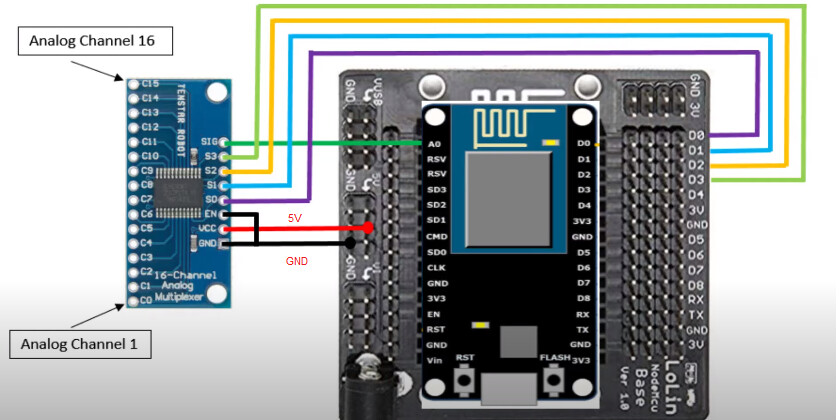
i have some issues using multiplexer 74HC4067 on my Node MCU V3 board, when im not using Blynk - everything’s fine. However when i try to use Blynk there are some reading sensors issues. MCU only has one analog input and i have 2 analog sensors(pH meter and resistance water level sensor)so im trying to implement multiplexer. I can’t understand why everything’s fine when im not using Blynk libraries, but when i try - there are reading issues. For example - when i try to read from pin C0 of the multiplexer, sensor is not reacting at all, when i try to read from pin C8 - everythings works perfectly, but on pin C9 there are data readings but they are some interrputs, for example value drops from 350 to 4 on it’s own, even though sensor is in the water. Any ideas what is the issue and how to fix it? For now im only trying to read sensor data from water level sensor using Blynk, after i fix that im going to try to implement pH sensor as well. I’m attaching wiring of the multiplexer(both nodeMCU and multiplexer are powered up by an external 5V power source, all GNDs are connected)and here is my code(in this example it’s for pin C0 of the multiplexer):
#define BLYNK_TEMPLATE_ID "TMPL8QG9Y_XR"
#define BLYNK_DEVICE_NAME "Led"

#define BLYNK_FIRMWARE_VERSION        "0.1.0"

#define BLYNK_PRINT Serial
#define BLYNK_DEBUG

#define APP_DEBUG

// Uncomment your board, or configure a custom board in Settings.h
//#define USE_SPARKFUN_BLYNK_BOARD
//#define USE_NODE_MCU_BOARD
//#define USE_WITTY_CLOUD_BOARD
//#define USE_WEMOS_D1_MINI

#include "BlynkEdgent.h"

int resistance;

BlynkTimer timer;

void multiplexer()
{

   digitalWrite(D0,LOW); digitalWrite(D1,LOW); digitalWrite(D2,LOW); digitalWrite(D3,LOW);
   resistance = analogRead(A0);

   Blynk.virtualWrite(V0, resistance);
}


void setup()
{
  pinMode(A0, INPUT);
  pinMode(D0,OUTPUT);
  pinMode(D1,OUTPUT);
  pinMode(D2,OUTPUT);
  pinMode(D3,OUTPUT);
  Serial.begin(9600);
  BlynkEdgent.begin();
  timer.setInterval(1000L, multiplexer);

}

void loop() {

  BlynkEdgent.run();
  timer.run();

}