NodeMCU Amica, compile and load sketch without error but do not run

Hi, in this project I am trying to use the NodeMCU Amica development board to carry out laboratory tests.

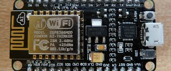
This is the photo of the module I’m testing.
image

As I already said, I compile and load the sketch without error, one messages appear on the serial monitor “[239] Connecting to CLEMENTE.NET
and, not happens nothing, The WiFi module LED remains off.
Is there anyone who has already solved this problem and can give me a hand?


This is the sketch I am trying

/*************************************************************
Download latest Blynk library here:

Blynk is a platform with iOS and Android apps to control
Arduino, Raspberry Pi and the likes over the Internet.
You can easily build graphic interfaces for all your
projects by simply dragging and dropping widgets.

Downloads, docs, tutorials: http://www.blynk.cc
Sketch generator:           http://examples.blynk.cc
Blynk community:            http://community.blynk.cc
Social networks:            http://www.fb.com/blynkapp
                            http://twitter.com/blynk_app

Blynk library is licensed under MIT license
This example code is in public domain.


This example runs directly on ESP8266 chip.

Note: This requires ESP8266 support package:

Please be sure to select the right ESP8266 module
in the Tools → Board menu!

Change WiFi ssid, pass, and Blynk auth token to run
Feel free to apply it to any other example. It’s simple!
*************************************************************/

/* Comment this out to disable prints and save space */
#define BLYNK_PRINT Serial
#include <ESP8266WiFi.h>
#include <BlynkSimpleEsp8266.h>

// You should get Auth Token in the Blynk App.
// Go to the Project Settings (nut icon).
char auth = “****************************************”;

// Your WiFi credentials.
// Set password to “” for open networks.
char ssid = “CLEMENTE.NET”;
char pass = “**************************”;

void setup(){
// Debug console
Serial.begin(9600);
Serial.print(“Started!”);
Blynk.begin(auth, ssid, pass);
if (Blynk.connected()) Serial.print(“BLYNK connesso”); else Serial.print(“BLYNK non connesso”);
}

void loop(){
Blynk.run();
Serial.print(“.”);
}


If that is the last you see on the serial monitor, then I would suspect you are having network connection issues… double check your password, perhaps try another network, or even change the SSID so as not to have any period in it (probably not an issue, but you never know)… your solution is in “trial/error/trial/success” laboratory method :stuck_out_tongue:

Very kind, thank you for having responded to me.
I think that is not a problem with connecting to the WiFi network, since the blue LED indicating the connection status when there is no connection should blink instead it remains off.

To ensure the module and access point work properly, I tested the same with another sketch; with this all worked well.

This is the sketch I used to test the module and the access point.


> /* ******************************************************************
>    Rui Santos
>    Complete project details at http://randomnerdtutorials.com  
>    ****************************************************************** */
> 
> #include <ESP8266WiFi.h>
> #include <WiFiClient.h>
> #include <ESP8266WebServer.h>
> #include <ESP8266mDNS.h>
> 
> MDNSResponder mdns;
> 
> // Replace with your network credentials
> const char* ssid = "CLEMENTE-NET";
> const char* password = "**********************";
> 
> ESP8266WebServer server(80);
> 
> String webPage = "";
> int gpio0_pin = 0;
> int gpio2_pin = 2;
> 
> void setup(void){
>     webPage += "<h1>ESP8266 Web Server</h1><p>Socket #1 <a href=\"socket1On\"><button>ON</button></a>&nbsp;<a href=\"socket1Off\"><button>OFF</button></a></p>";
>     webPage += "<p>Socket #2 <a href=\"socket2On\"><button>ON</button></a>&nbsp;<a href=\"socket2Off\"><button>OFF</button></a></p>";
>     //
>     // preparing GPIOs
>     //
>     pinMode(gpio0_pin, OUTPUT);
>     digitalWrite(gpio0_pin, LOW);
>     pinMode(gpio2_pin, OUTPUT);
>     digitalWrite(gpio2_pin, LOW);
>     
>     delay(1000);
>     Serial.begin(9600);
>     WiFi.begin(ssid, password);
>     Serial.println("");
> 
>     // 
>     // Wait for connection
>     //
>     while(WiFi.status() != WL_CONNECTED){
>         delay(500);
>         Serial.print(".");
>         }
>     Serial.println("");
>     Serial.print("Connected to ");
>     Serial.println(ssid);
>     Serial.print("IP address: ");
>     Serial.println(WiFi.localIP());
>   
>     if(mdns.begin("esp8266", WiFi.localIP())) Serial.println("MDNS responder started");
>   
>     server.on("/", [](){server.send(200, "text/html", webPage);});
>     
>     server.on("/socket1On", [](){
>         server.send(200, "text/html", webPage);
>         digitalWrite(gpio0_pin, HIGH);
>         delay(1000);
>         });
>         
>     server.on("/socket1Off", [](){
>         server.send(200, "text/html", webPage);
>         digitalWrite(gpio0_pin, LOW);
>         delay(1000); 
>         });
>         
>     server.on("/socket2On", [](){
>         server.send(200, "text/html", webPage);
>         digitalWrite(gpio2_pin, HIGH);
>         delay(1000);
>         });
>   
>     server.on("/socket2Off", [](){
>         server.send(200, "text/html", webPage);
>         digitalWrite(gpio2_pin, LOW);
>         delay(1000); 
>         });
>   
>     server.begin();
>     Serial.println("HTTP server started");
>     }
>  
>     void loop(void){
>       server.handleClient();
>       } 

I do not know if you’ve noticed that I’ve added a line to the original Blynk sketch to see where this stops. The line of code I add does not ever run. I think it is a problem setting the module parameters and that they block the sketch operation.

The sketch that worked okay has a different network SSID from your Blynk sketch. One has a period and the other a hyphen.
Is this intentional, have you modified your SSID as @Gunner suggested?

Pete.

Problem solved, sketch works properly SSID was incorrect as you suggested, probably inadvertently I typed the dash instead of the dot.
What led me to think of a code block was the status LED of the WiFi module that was left off.
In order to improve the libraries, in the next release it would be interesting to implement natively the status of the connection on the GP2 pin, “pin ON: network connected”, "pin pulsed " 250ms ON 250ms OFF ": network disconnected, "pin pulsed “250ms ON 100ms OFF 250ms ON 400ms OFF” network connection error.
I thank your for your courteous availability.

1 Like