Please help. I want to use two button widgets set to push to control an LED widget. One push button to toggle LED on and the second to toggle LED off.
Peter
Please help. I want to use two button widgets set to push to control an LED widget. One push button to toggle LED on and the second to toggle LED off.
Peter
What hardware are you using?
What code do you have running on the hardware at the moment?
Have you looked at the Sketch Builder examples?
Pete.
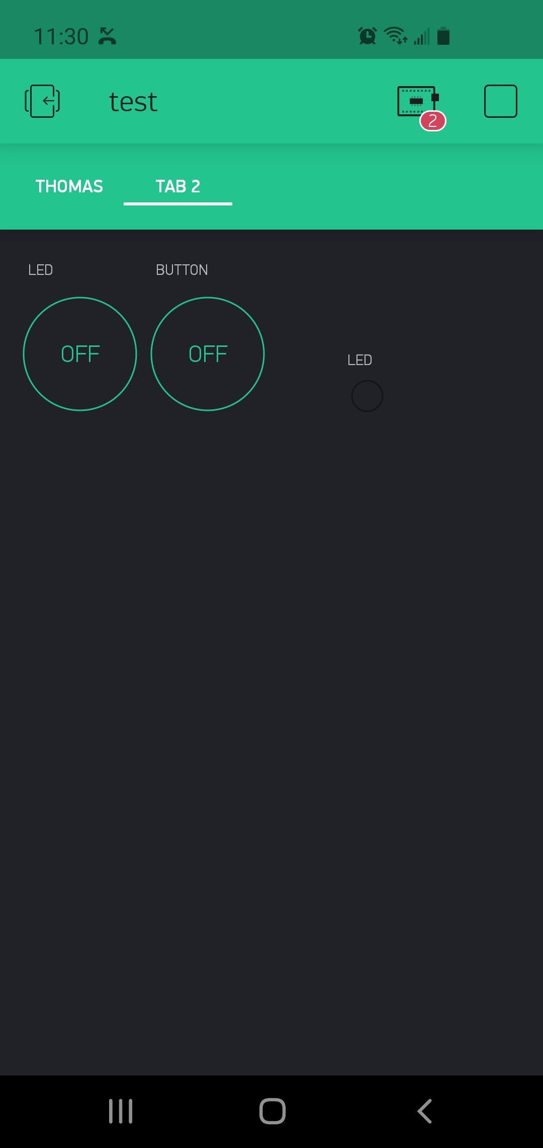
Thank you for responding. I attached the screen. Both buttons are set to “push”. I would like them to toggle the LED on and off. One button push would turn it on and the other turn it off. I am using an ESP32. I run the usual Blynk code. I have not seen an example that can do this.
I assume by this that you mean a simple sketch with just Blynk.run in the void loop and that your button widgets are attached to digital rather than virtual pins?
I’d suggest that you attach the widgets to virtual pins, add the necessary BLYNK_WRITE(vPin) callback functions and use one function to perform a Blynk.virtualWrite(vPin,255) to turn your LED widget on and a Blynk.virtualWrite(vPin,0) to turn your LED widget off.
Pete.
I am new to buttons. I did this, but there is an error.
int ButtA;
int ButtA;

void setup() {
  Serial.begin(115200);
  Blynk.begin(auth, ssid, pass);
  ButtA.attach(13);
  ButtB.attach(2);
}
BLYNK_WRITE(V1)
{
  ButtA.write(param.asInt());
}
BLYNK_WRITE(V2)
{
  ButtB.write(param.asInt());
}

void loop() {
 Blynk.run();

}
@Peter2 please edit your post, using the pencil icon at the bottom, and add triple backticks at the beginning and end of your code so that it displays correctly.
Triple backticks look like this:
```
Pete.
Deliberate mistake?
In a way it makes no difference with your code, as these variables aren’t needed.
Not sure what you’re trying to do here, but you should not have those two lines of code, as your two button widgets will be connected to virtual, not physical pins.
Not sure what you’re trying to do here either.
It doesn’t matter whether the button is sending a 1 (on) or a 0 (off), because they are set to push mode, so when the button is being pressed or released you want to turn your LED widget on with the on button and off with the off button.
As a result, you don’t need to capture the button value with the param.asInt command.
You ignored this piece of advice.
Pete.
I did not get to the virtualWrite yet. I need to have the buttons control relay modules via physical pins.
That’s somewhat different from your original description of your requirements…
and none of your code will achieve your new functional goals.
Pete.
I got this code to control digital pins and toggle the LED widget. It was working, but now I can only get digital pin 2 to work. I cannot get any other pins to work. Using an ESP32 dev board.
void setup()
{
  Serial.begin(115200);
  Blynk.begin(auth, ssid, pass);
}

BLYNK_WRITE(V0) {
 int pinValue = param.asInt();
 if (pinValue == 255)
 {
    digitalWrite(2, HIGH);
    Blynk.virtualWrite(V1, 255);
    Blynk.virtualWrite(V2, 0);
    delay(500);
    digitalWrite(2, LOW);
  }
}

BLYNK_WRITE(V4) {
 int pinValue = param.asInt();
 if (pinValue == 255)
 {
    digitalWrite(13, HIGH);
    Blynk.virtualWrite(V1, 0);
    Blynk.virtualWrite(V2, 255);
    delay(500);
    digitalWrite(13, LOW);
  }
}

void loop()
{
  Blynk.run();
}
You now appear to have changed your requirements yet again.
Previously it was two button widgets to control 1 LED widget. then two buttons to control relay modules (plural, but you don’t elaborate further) attached to digital pins.
You now appear to have two button widgets, two LED widgets and two relays.
I’m assuming taht your setup is…
Button widget A attached to vPin 0
Button widget B attached to vPin 4
LED widget A attached to vPin 1
LED widgetB attached to vPin 2
Relay A attached to physical pin 2
Relay B attached to physical pin 13
Is this correct?
If so, what is the function of each of the button widgets?
How are the button widgets configured (push./switch and what are the off/on values)?
What are each of the LED widgets meant to indicate?
Are your relay modules activated (the coil energised) by a HIGH or a LOW logic level signal?
The things that leap out a me are…
You’ll only get a 255 value from your button widget if you’ve specifically set tis up. The default is 0 for off and 1 for on.
Secondly, you have no pinMode statements in your void setup, so I doubt very much if your relays will respond to the digitalWrite commands.
Thirdly, you have delays in your BLYNK_WRITE statements, which as you know (from reading the “keep your void loop clean” document) should be avoided.
Pete.
Thanks. the two buttons controlling an LED has been answered. I will make a new post regarding my new issue.
Okay, with your next issue I’d suggest providing a better and more accurate description of your issue and of your requirements.
Pete.