Need help with dimming with blynk

Hello all,
I know it is not new as a topic, but I really need your help because, after reading all the documentation possible and have tried almost anything, I am stuck with my project. What I want to achieve: With an Arduino Mega 2650 board with Ethernet shield and blynk running locally on a raspberry pi 3, I need to dim 7 (LED) bulbs.
For that, I have bought the following dimmer from AliExpress ( https://www.aliexpress.com/item/AC-Light-Dimmer-Module-for-PWM-control-1-Channel-3-3V-5V-logic-AC-50-60hz/32802025086.html?spm=a2g0s.9042311.0.0.27424c4dchWRVK ). It has zero-cross detection. I have adapted some sample code that I have found in the blynk community but still cannot make it working. I want to control everything from my iPhone 6s.
The dimmer is connected as follows:

  • Dimmer Vcc to 5V pin on Arduino Mega
  • GND dimmer pin to Arduino GND pin
  • Zero-crossing pin to A0 pin on Mega 2650
  • Dimmer PWM pin to D3 pin on Arduino Mega.
    Built the blynk project, managed to connect to the device but, when trying to dim the bulb, I got no dimming. The bulb is always on, regardless where the slider is. I have to mention though that when I reach with the slider to the left side, I got the bulb flickering a bit but the intensity of the light remains unchanged. Also worthing to mention, there is a small blue LED on the dimmer that indicates the dimming progress. That LED is dimmed while moving the slider.
    The dimmer board is working, I have tested the triac and it works fine.
    As I spent weeks to understand what’;s going on without any success, here I am asking your help and guidance.
    Below you can find my code for reference.
    Thank you very much in advance for your time and support.
#define BLYNK_PRINT Serial    // Comment this out to disable prints and save space
#include <SPI.h>
#include <Ethernet.h>
#include <BlynkSimpleEthernet.h>
#include  <TimerOne.h> 

volatile int i=0;               // Variable to use as a counter volatile as it is in an interrupt
volatile boolean zero_cross=0;  // Boolean to store a "switch" to tell us if we have crossed zero
int AC_pin = 13;                // Output to Opto Triac
int dim = 0;                    // Dimming level (0-128)  0 = on, 128 = 0ff
int inc=1;                      // counting up or down, 1=up, -1=down

int brightness = 120;

int freqStep = 78; //75 initial value   // This is the delay-per-brightness step in microseconds.
                      // For 60 Hz it should be 65
// It is calculated based on the frequency of your voltage supply (50Hz or 60Hz)
// and the number of brightness steps you want. 
// 
// Realize that there are 2 zero-crossing per cycle. This means
// zero crossing happens at 120Hz for a 60Hz supply or 100Hz for a 50Hz supply. 

// To calculate freqStep divide the length of one full half-wave of the power
// cycle (in microseconds) by the number of brightness steps. 
//
// (120 Hz=8333uS) / 128 brightness steps = 65 uS / brightness step
// (100Hz=10000uS) / 128 steps = 75uS/step

int value;

#define W5100_CS  10
#define SDCARD_CS 4

// You should get Auth Token in the Blynk App.
// Go to the Project Settings (nut icon).
char auth[] = "xxxxxxx";

IPAddress server_ip (x, x, x, x);

// Mac address should be different for each device in your LAN
byte arduino_mac[] = { 0xDE, 0xED, 0xBA, 0xFE, 0xFE, 0xED };
IPAddress arduino_ip (x, x, x, x);
IPAddress dns_ip     (193, 231, 252, 1);
IPAddress gateway_ip (10, 130, 27, 255);
IPAddress subnet_mask(255, 255, 255,   0);

void setup()
{
  Serial.begin(115200);
  pinMode(SDCARD_CS, OUTPUT);
  digitalWrite(SDCARD_CS, HIGH); // Deselect the SD card
  pinMode(AC_pin, OUTPUT);                          // Set the Triac pin as output
  attachInterrupt(0, zero_cross_detect, RISING);    // Attach an Interupt to Pin 2 (interupt 0) 
//  attachInterrupt(0, light, FALLING);
  Timer1.initialize(freqStep);                      // Initialize TimerOne library 
  Timer1.attachInterrupt(dim_check, freqStep);   
  Blynk.begin(auth, server_ip, 8080, arduino_ip, dns_ip, gateway_ip, subnet_mask, arduino_mac);
}

void zero_cross_detect() {    
  zero_cross = true;               
  i=0;
  digitalWrite(AC_pin, LOW);       // turn off TRIAC (and AC)
}
// Turn on the TRIAC at the appropriate time
void dim_check() {
                 
  if(zero_cross == true) { 
              
    if(i>=dim) {                     
      digitalWrite(AC_pin, HIGH); // turn on light       
      i=0;  // reset time step counter                         
      zero_cross = false; //reset zero cross detection
    } 
    else {
      i++; // increment time step counter                     
    }                                
  }                                  
}   

void loop()
{
  Blynk.run();
}
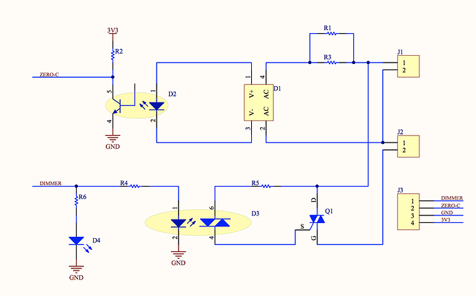
I forgot to add the schematic diagram of the PWM dimmer. Please find it attached:

Firstly, are you using mains LED bulbs that specifically state that they’re dimable? (Most aren’t capable of being dimmed).

Secondly, you’re attaching an interrupt to an analogue pin (A0). I don’t think that this is possible. Whatever pin you do end-up using for your zero-crossing detection, it probably needs to have a pin mode state demo defining it as an input.

Thirdly, you’re using timers in your code, but don’t have timer.run in your void loop.

Pete.

This sketch is using a different type of timer… but since it is copied code, the user may not be aware of the timer differences or how to code enough to troubleshoot.

@mihai.costache we primarily try to help new users learn about Blynk, not troubleshoot/teach code… Aside from the obvious “not working” have you any further information? We don’t have your hardware and can’t exactly look over your shoulder :stuck_out_tongue:

Aside from the aforementioned timer and pin issues, perhaps start with dimming a simple LED to test whether the PWM function works

Hi Pete. Thank you very much for your fast reply. Yes, I have tried both dimmable LED bulbs for 220V and normal incandescence bulb and got the same outcome for both.
Thanks for the advice with the code, I will address it accordingly. As I am new to this, could you suggest me a pin to use for the zero-crossing?

Hi Gunner,
thank you very much for your reply. What do you mean, the code is using a different type of timer? I have downloaded the TimerOne library the coder indicated in his example.
Not working means, as I described in my initial message, that I cannot dim the bulb (regardless dimmable LED one or normal type), and that means when I move the slider, the light intensity remains the same, pretty much at the same (maximum) intensity, the only thing I can see is, when I dim the bulb to the minimum, it starts flickering. Can you please let me know what additional information do you need?

Thank you once again.

With a Mega, interrupts can be enabled on any of the DIGITAL pins (as opposed to Analogue pins).
http://playground.arduino.cc/code/interrupts

The Blynk library contains a built-in timer function, which is a variation on the simpletimer library. I’d assumed that this was what you were using, as I hadn’t spotted that you’d included the OneTimer library (good spot @Gunner).
If it was me, I’d go with the Blynk Timer that’s built into the library if I were you. If you search the forum you’ll see some great examples of how best to use the timer.

Pete.

Hello again Blynkers,
I really need your help here. After a couple of weeks spent reading articles and code, I managed to make the code running to dim a light bulb (both normal and LED ones). The code looks like below. My kind ask to you is now, to guide me how can I dim multiple bulbs, using the same Arduino Mega 2650 and, for each bulb, a PWM dimmer as presented above in this thread.
I have tried to include in the zero_cross_detect function the code for the second bulb, but does not as desired. The behavior is the following:

  • sliding the second slider (V5) I can dim the second bulb
  • sliding the first slider (V4) then both bulbs get dimmed and, after a while, if I go with this slider to the minimum, Arduino freezes and both bulbs flicker really bad.

Forgot to mention that I have googled a lot but wasn’t able to find an answer for this issue

I know it might not be a blynk per se issue but I really need your help here. Thank you very much in advance for guidance and patience.

#include <SPI.h>
#include <Ethernet.h>
#include <BlynkSimpleEthernet.h>
#include <TimeLib.h>
#include <WidgetRTC.h>
#include <SimpleTimer.h>;

#define W5100_CS  10
#define SDCARD_CS 4

#define triacApin1 6
int power1 = 3;
int power2 = 3;
int dimtime1;
int dimtime2;

char auth[] = "xxxxx";


IPAddress server_ip (x, x, x, x);
byte arduino_mac[] = { 0xDE, 0xED, 0xBA, 0xFE, 0xFE, 0xED };
IPAddress arduino_ip (x, x, x, x);
IPAddress dns_ip     (x, x, x, x);
IPAddress gateway_ip (x, x, x, x);
IPAddress subnet_mask(255, 255, 255,   0);


bool isFirstConnect = true;

void zero_cross_detect(){
    dimtime1 = (100 * power1);      
    delayMicroseconds(dimtime1);    // Wait till firing the TRIAC
    digitalWrite(triacApin1, HIGH);   // Fire the TRIAC
    delayMicroseconds(10);         // triac On propogation delay (for 60Hz use 8.33)
    digitalWrite(triacApin1, LOW);    // No longer trigger the TRIAC (the next zero crossing will swith it off) TRIAC    

// Code for the second dimmer
  dimtime2 = (100 * power2);
  delayMicroseconds(dimtime1);
  digitalWrite(triacApin2, HIGH);
  delayMicroseconds(10);
  digitalWrite(triacApin2, LOW);
  
}

BLYNK_WRITE(V4) {
  power1 = param.asInt();
}

BLYNK_WRITE(V5) {
  power2 = param.asInt();
}

BLYNK_CONNECTED(){
  if (isFirstConnect){
    Blynk.virtualWrite(V4, 5);
    isFirstConnect = false;    
  }
}

void setup() {
  Serial.begin(115200);
  Blynk.begin(auth, server_ip, 8080, arduino_ip, dns_ip, gateway_ip, subnet_mask, arduino_mac);
  while (Blynk.connect() == false){}
  Serial.println("Connected to Blynk");
  pinMode(triacApin1, OUTPUT);
  digitalWrite(triacApin1, LOW);
  attachInterrupt(digitalPinToInterrupt(3), zero_cross_detect, RISING);
}


void loop() {
  Blynk.run();
  timer.run();
}

I don’t think the code you’ve posted is the code that’s producing the results you’ve described in your post, because this code won’t compile…

triacApin2 isn’t defined/declared
You’re calling timer.run in your void loop, but you haven’t declared a timer in void setup()

It’s difficult to help you figure-out your problem if you don’t give us the correct code :stuck_out_tongue_winking_eye:

Pete.

HI Pete,
thank you for your quick reply. Indeed the code I’ve posted earlier had couple of errors in it.
Forgot to mention that the zero-cross pin is connected to D3 on Arduino board as the output for thyristors (PWM) are connected to D6 and D7.
Please find the tested one here:

#include <SPI.h>
#include <Ethernet.h>
#include <BlynkSimpleEthernet.h>
#include <TimeLib.h>
#include <WidgetRTC.h>

#define W5100_CS  10
#define SDCARD_CS 4

#define triacApin1 6
#define triacApin2 7
int power1 = 3;
int power2 = 3;
int dimtime1;
int dimtime2;

char auth[] = "xxxxx";

IPAddress server_ip (xx, xx, xx, xx);
byte arduino_mac[] = { 0xDE, 0xED, 0xBA, 0xFE, 0xFE, 0xED };
IPAddress arduino_ip (xx, xx, xx, xx);
IPAddress dns_ip     (193, 231, 252, 1);
IPAddress gateway_ip (10, 130, 27, 255);
IPAddress subnet_mask(255, 255, 255,   0);


// Variables used to display date and time

bool isFirstConnect = true;

void zero_cross_detect(){
    dimtime1 = (100 * power1);      
    delayMicroseconds(dimtime1);    // Wait till firing the TRIAC
    digitalWrite(triacApin1, HIGH);   // Fire the TRIAC
    delayMicroseconds(10);         // triac On propogation delay (for 60Hz use 8.33)
    digitalWrite(triacApin1, LOW);    // No longer trigger the TRIAC (the next zero crossing will swith it off) TRIAC    

// Code for the second dimmer
  dimtime2 = (100 * power2);
  delayMicroseconds(dimtime2);
  digitalWrite(triacApin2, HIGH);
  delayMicroseconds(10);
  digitalWrite(triacApin2, LOW);
  
}

BLYNK_WRITE(V4) {
  power1 = param.asInt();
}

BLYNK_WRITE(V5) {
  power2 = param.asInt();
}

BLYNK_CONNECTED(){
  if (isFirstConnect){
    Blynk.virtualWrite(V4, 5);
    isFirstConnect = false;    
  }
}

void setup() {
  Serial.begin(115200);
  Blynk.begin(auth, server_ip, 8080, arduino_ip, dns_ip, gateway_ip, subnet_mask, arduino_mac);
  while (Blynk.connect() == false){}
  Serial.println("Connected to Blynk");
  pinMode(triacApin1, OUTPUT);
  pinMode(triacApin2, OUTPUT);
  digitalWrite(triacApin1, LOW);
  digitalWrite(triacApin2, LOW);
  attachInterrupt(digitalPinToInterrupt(3), zero_cross_detect, RISING);
}


void loop() {
  Blynk.run();
}

I would have thought that if you’re using two separate single channel boards then you shouldn’t be using the same pin for your zero crossing detection on both boards.

Try using different pins for the ZCD for each board, and add the appropriate second interrupt, then split your ZCD function, something like this…

  attachInterrupt(digitalPinToInterrupt(3), zero_cross_detect_1, RISING);
  attachInterrupt(digitalPinToInterrupt(???), zero_cross_detect_2, RISING);


void zero_cross_detect_1(){
    dimtime1 = (100 * power1);      
    delayMicroseconds(dimtime1);    // Wait till firing the TRIAC
    digitalWrite(triacApin1, HIGH);   // Fire the TRIAC
    delayMicroseconds(10);         // triac On propogation delay (for 60Hz use 8.33)
    digitalWrite(triacApin1, LOW);    // No longer trigger the TRIAC (the next zero crossing will swith it off) TRIAC   
}
 

void zero_cross_detect_2(){
    dimtime2 = (100 * power2);
    delayMicroseconds(dimtime2);
    digitalWrite(triacApin2, HIGH);
    delayMicroseconds(10);
    digitalWrite(triacApin2, LOW);
}

Pete.

Hi Pete,
thank you for your reply. I have two options:

  • separate (8) ZCD boards as you mentioned
  • one board having the same Zero Cross and 8 inputs and outputs. Frankly I would prefer to use this one mainly because of the space occupied and because, using one ZCD for each board, that means I should use 2 Arduino Mega instead of one for my automation.
    Do you think there is some way to cope with only one ZCD serving all 8 zones?

Thank you once again.

I’m not exactly sure what you’re asking here. You’ve said that you’re using two boards at the moment, but you’re connecting the ZCD wires together, and it’s not working.
Try what I suggested with using different pins for each of the (currently) two ZCD outputs and see if it works.

Once you have your answer then you’ll have a better idea of how to proceed.

Pete.

Hi Pete,
OK, I will try as you suggested and come back with a feedback.
What I was trying to say is that, in the end, I will have to control (dim) 8 zones with my automation. I have tried first with two but eventually I need to extend to 8 zones. Using one pin for each ZCD, means I’m gonna need 8 pins for this, and one Arduino Mega supports only 6 pins to attachInterrupts on them (2, 3, 18, 19, 20, 21). That means I will have to use two Arduino Mega boards in order to accommodate all 8 ZCDs I need.
But, as I mentioned, I will try to see if it works as you recommended and I will come back with a reply.
Once again, thank you.

Hi Pete,
I have tried, unfortunately the result is the same. One slider (the second in the code) dims correctly one bulb, but when slide the first one, both bulbs get dimmed and, once slide completely to the left, then both bulbs starts to flicker and the board gets blocked, the app goes unresponsive. :frowning:
Any other hints?

Thank you.

Here is the sample code for reference:

#define BLYNK_PRINT Serial    // Comment this out to disable prints and save space
#include <SPI.h>
#include <Ethernet.h>
#include <BlynkSimpleEthernet.h>
#include <TimeLib.h>
#include <WidgetRTC.h>

#define W5100_CS  10
#define SDCARD_CS 4

#define triacApin1 12
#define triacApin2 13
int power1 = 3;
int power2 = 3;
int dimtime1;
int dimtime2;

char auth[] = "xxxxxxx";

IPAddress server_ip (x, x, x, x);
byte arduino_mac[] = { 0xDE, 0xED, 0xBA, 0xFE, 0xFE, 0xED };
IPAddress arduino_ip (x, x, x, x);
IPAddress dns_ip     (193, 231, 252, 1);
IPAddress gateway_ip (10, 130, 27, 255);
IPAddress subnet_mask(255, 255, 255,   0);

bool isFirstConnect = true;

void zero_cross_detect1(){
    dimtime1 = (100 * power1);      
    delayMicroseconds(dimtime1);    // Wait till firing the TRIAC
    digitalWrite(triacApin1, HIGH);   // Fire the TRIAC
    delayMicroseconds(10);         // triac On propogation delay (for 60Hz use 8.33)
    digitalWrite(triacApin1, LOW);    // No longer trigger the TRIAC (the next zero crossing will swith it off) TRIAC    
}
void zero_cross_detect2(){
// Code for the second dimmer
  dimtime2 = (100 * power2);
  delayMicroseconds(dimtime2);
  digitalWrite(triacApin2, HIGH);
  delayMicroseconds(10);
  digitalWrite(triacApin2, LOW);  
}

BLYNK_WRITE(V4) {
  power1 = param.asInt();
}

BLYNK_WRITE(V5) {
  power2 = param.asInt();
}

//BLYNK_CONNECTED(){
//  if (isFirstConnect){
//    Blynk.virtualWrite(V4, 5);
//    Blynk.virtualWrite(V5, 5);
//    isFirstConnect = false;    
//  }
//}

void setup() {
  Serial.begin(115200);
  Blynk.begin(auth, server_ip, 8080, arduino_ip, dns_ip, gateway_ip, subnet_mask, arduino_mac);
  while (Blynk.connect() == false){}
  Serial.println("Connected to Blynk");
  pinMode(triacApin1, OUTPUT);
  pinMode(triacApin2, OUTPUT);
//  digitalWrite(triacApin1, LOW);
//  digitalWrite(triacApin2, LOW);
  attachInterrupt(digitalPinToInterrupt(18), zero_cross_detect1, RISING);
  delay(10);
  attachInterrupt(digitalPinToInterrupt(19), zero_cross_detect2, RISING);
}


void loop() {
  Blynk.run();
}

How exactly are your boards wired now, and how are the sliders set-up in the app?

Pete.

OK so, I have an Arduino Mega 2650 that is connected to a power supply (12V) by a jack. The power supply provides 12Vcc and 5Vcc. From the 5Vcc side, I power the dimmers (https://www.aliexpress.com/item/AC-Light-Dimmer-Module-for-PWM-control-1-Channel-3-3V-5V-logic-AC-50-60hz/32802025086.html?spm=a2g0s.9042311.0.0.27424c4di4d7ds).
Each dimmer has on the output a bulb, and the dimmer input is connected to 220V.
Zero-crossing pins from the dimmers are connected one to pin 18 and the other one to pin 19.
PWM pins are connected to pin 12 and 13 on Arduino board.
The sliders are defined in the app as connected to V4 respectively V5. They are set to retrieve valued from 85 to 5, I set them to send values all the time not only to release.
That is the configuration.

Three final thoughts, then I’m out of ideas…

  1. You don’t have a pinmode defined for the two zero cross pins
  2. Pin 13 on the Arduino is a slightly ‘special’ pin, so might be best avoided
  3. Arduino PWM goes from 0-255, but you’re only using 5-85 (or 3-85 if you use your initial power1 & power2 values). I assume that there’s a good reason that’s something to do with your dimmer hardware?

One final thought, I assume you haven’t enabled the mapping function on either of your sliders? (that’s the squiggly line inside a circle that linked your minimum and maximum output values).

Pete.

Hi Pete,
I set the pinmode defined for the zero crosses.

  pinMode(18, INPUT_PULLUP);
  pinMode(19, INPUT_PULLUP);

in the setup() function.
I have moved the PWM to pin 11 instead of pin 13.
I activated the mapping function on the sliders.

The pattern still remains. :frowning:
In regards of the PWM if I modify the values to be from 0 to 255 then, once I dim the light and passed mid of the slider, the bulb starts flickering and the Arduino gets stuck. I have read in some examples that the values should be set like that. Nevertheless I have tried also with 0 to 255 after the above-mentioned and there is the same behavior described.
Thank you for trying. I will dig into it tomorrow…

Just a wild ass guess, and probably won’t be the solution, but maybe try changing them to volatile int. I think I read somewhere once that a variable should be declared as volatile whenever its is used/changed in an interrupt service routine.