I am having trouble with getting the value of pH in the Blynk application. I already got the pH reading in the serial monitor but in the Blynk Application, there in none. I am pretty sure the codes that I am using is the problem.
Here are my Codes for Arduino UNO:
#include <stdlib.h>
#include <SoftwareSerial.h>
SoftwareSerial nodemcu(2,3);

#define SensorPin 0          //pH meter Analog output to Arduino Analog Input 0
unsigned long int avgValue;  //Store the average value of the sensor feedback
float b;
int buf[10],temp;

// for float value to string converstion
int f;
  float val; // also works with double.
  char buff2[10];
  String valueString = "";
  String Value = "";

void setup()
{
  pinMode(13,OUTPUT);
  Serial.begin(9600);
  nodemcu.begin(9600);
}
void loop()
{
  for(int i=0;i<10;i++)       //Get 10 sample value from the sensor for smooth the value
  {
    buf[i]=analogRead(SensorPin);
    delay(10);
  }
  for(int i=0;i<9;i++)        //sort the analog from small to large
  {
    for(int j=i+1;j<10;j++)
    {
      if(buf[i]>buf[j])
      {
        temp=buf[i];
        buf[i]=buf[j];
        buf[j]=temp;
      }
    }
  }
  avgValue=0;
  for(int i=2;i<8;i++)                      //take the average value of 6 center sample
    avgValue+=buf[i];
  float phValue=(float)avgValue*5.0/1024/6; //convert the analog into millivolt
  phValue=3.5*phValue;                      //convert the millivolt into pH value
     Value =  dtostrf(phValue, 4, 2, buff2);  //4 is mininum width, 6 is precision
   valueString = valueString + Value +",";
   Serial.println(valueString);
   nodemcu.println(valueString);
  valueString = "";
 delay(1000);

}
And here are my codes for ESP8266 NodeMCU:
#define BLYNK_TEMPLATE_ID "TMPLysXmi6X_"
#define BLYNK_DEVICE_NAME "PH and EC Sensor with Blynk2"
#define BLYNK_AUTH_TOKEN "e-dg7RhcNsLcXfxIfnMFtIrcQyFAXF_O"

#define BLYNK_PRINT Serial
#include <ESP8266WiFi.h>
#include <BlynkSimpleEsp8266.h>
#include <SoftwareSerial.h>

// PH sensor
WidgetLCD lcd (V0);
String data;
String I;
char auth[] = "e-dg7RhcNsLcXfxIfnMFtIrcQyFAXF_O";

// Your WiFi credentials.
// Set password to "" for open networks.
char ssid[] = "My wifi";
char pass[] = "My password";


BlynkTimer timer;
String myString; // complete message from arduino, which consistors of snesors data
char rdata; // received charactors


// This function sends Arduino's up time every second to Virtual Pin (1).
// In the app, Widget's reading frequency should be set to PUSH. This means
// that you define how often to send data to Blynk App.
void myTimerEvent()
{
  // You can send any value at any time.
  // Please don't send more that 10 values per second.
  Blynk.virtualWrite(V0, millis() / 1000); //ph
}


void setup()
{
  // Debug console
  Serial.begin(9600);

  Blynk.begin(auth, ssid, pass);

    timer.setInterval(1000L,sensorvalue1); //ph

}

void loop()
{

   if (Serial.available() == 0 )
   {
  Blynk.run();
  timer.run(); // Initiates BlynkTimer
   }

  if (Serial.available() > 0 )
  {
    rdata = Serial.read();
    myString = myString+ rdata;
   Serial.print(rdata);
    if( rdata == '\n')
    {
I = getValue(myString, ',', 0);
  myString = "";
  lcd.print(0,0,"pH Value:");

 // Serial.println(I);
//lcd.print(0,0,"pH Value:");
    }
  }

}


void sensorvalue1()
{
data = data + I;
lcd.print(0,0,"pH Value:");
 lcd.print(0,1,data);
 data = "";

}


String getValue(String data, char separator, int index)
{
    int found = 0;
    int strIndex[] = { 0, -1 };
    int maxIndex = data.length() - 1;

    for (int i = 0; i <= maxIndex && found <= index; i++) {
        if (data.charAt(i) == separator || i == maxIndex) {
            found++;
            strIndex[0] = strIndex[1] + 1;
            strIndex[1] = (i == maxIndex) ? i+1 : i;
        }
    }
    return found > index ? data.substring(strIndex[0], strIndex[1]) : "";
}
The serial monitor of which device, the Uno or the ESP8266?
Is the ESP8266 showing as being Online in Blynk?
Is this your sketch, or one that you’ve obtained from someone else? How good are your C++ coding skills?
Is there a good reason why you’ve chosen this hardware combination?
If so, is there any reason why you haven’t gone for the more conventional approach of using the ESP8266 as an AT WiFi adapter for the Uno?
I’d recommend throwing the Uno in the bin and connecting the PH meter directly to the NodeMCU. But if you have a valid reason for not doing that then the other (less desirable, but more conventional) approach is to run the factory AT firmware on an ESP8266 based device. This is usually done with an ESP-01 board rather than a NodeMCU, but both are possible provided you can find the AT firmware to upload to the board.
More info here…
At the moment, your NodeMCU sketch is a total mess.
You are waiting for serial input from the Uno in your void loop and serial printing the characters one at a time as they arrive. The code attempts to assemble these into a string called I, which is then sent to Blynk. You should NEVER have send data to Blynk in your void loop
Getting Blynk to co-exist with a function that listens for incoming serial data from another source such as the Uno is extremely difficult, and should be avoided in my opinion.
By far the best, and probably simplest, approach is to scrap the Uno and use the NodeMCU to read the PH sensor.
Hello sir, the reason why I will use Arduino is because I am also using TDS sensor. I’m sorry my description is incomplete. And also we will add for float sensor.
Do these additional sensors require analog inputs?
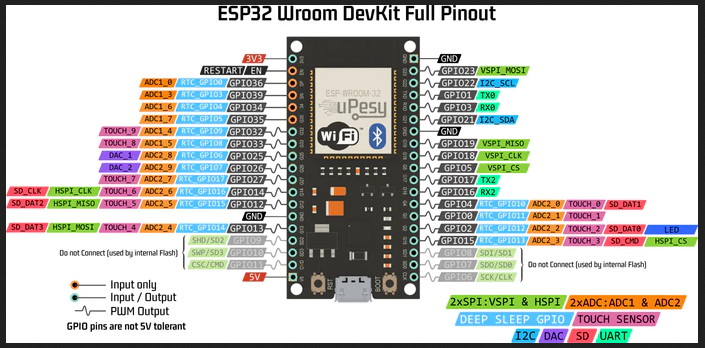
If not then you may be able to simply use the NodeMCU. Otherwise, throw the Uno in the bin, put the NodeMCU aside for future use and use an ESP32 instead.
You can see that there are 18 pins that can be used as Analog inputs, but only 8 of them can be used when using WiFi (Blynk uses WiFi, so thee are 8 usable analog inputs).
Some of the other pins should be avoided, and some are input only, but you should have plenty of available pins.
When you are using Analog inputs it’s important to keep your wire lengths as short as practical.
You need to improve your C++ coding skills, so while you’re waiting for your ESP32 to arrive I’d suggest that you watch some YouTube tutorials then take a look at your existing NodeMCU sketch and see what basic mistakes you’ve made - such as your myTimerEvent function never being called, and having duplicate code in your void loop and sensorvalue1 functions.
Also, using indents in your code, and adding sensible comments about what each part of the code does, will allow you to understand it much better.
I’d suggest that you search this forum for other similar projects to use as a foundation for your code, rather than using your existing sketches, as they are awful.
I made my alkalinity controller which uses a ph sensor this way. I used an Atlas Scientific probe with the stamp connected to an arduino mega (the reason for using the mega is I needed to control some paristaltic pumps and stepper motor pumps). Atlas are kind enough to publish the working code for the mega which works using one of the serials of the mega. I connected the mega via i2c to an esp32 which deals with the user interface side of things(Blynk). So basically the esp sends all the required interface via i2c to the mega which runs the probe and pumps. The mega in return then sends resultant readings via i2c back to the esp which displays on my phone.