Hello friends,
I’m trying to search the topics about to use 16 channel relays with NodeMcu and blynk.
But nothing to get my need, I am new to blynk and esp8266, I had experienced the blynk app use with 4 relays. It works!
Please suggest me the topic related to use 16 channel relays for home automation projects.
Thank’s,
You need to start using ESP32 if you need to control 16 relays. With ESP8266 you can control may be 10(max) because there are few pins which cannot be used as output.
Else you should use an IO expander to gain more pins and control it with I2C.
2 Likes
Obviously the NodeMCU doesn’t have 16 useable GPIO pins that you can use.
An ESP32 only really has 14 useable output GPIO’s, as some of the others go HIGH on boot-up, which may not be what you want when you have relays connected to them (depending on your relays and your project).
You could use two or more MCUs, which is fairly straight forward in Blynk - just add more devices to your project. When you add a control widget to your project you can assign which device it’s connected to, so a user of the interface won’t know that there are two devices being used. The only slight complication is if you want to have a widget which controls all of the relays. In this situation you’d need to use some Bridge code on one of your devices.
The other option is to use multiplexor hardware, or an I2C port extender based on something like the PCF8575 or MCP23017 chips.
I actually have some Open-Smart PCF8575 boards like this on their way via a slow boat from China:
When they arrive I’ll do some testing and share my results.
Pete.
3 Likes
Thanks Pete, I have PCF8575 Module Now its easy for me to search on youtube for Learning.
Thanks for help!
1 Like
Hello,
With this we only use two pins for communication, and we can get rid of the short pulse that nodemcu produces while booting !! Which activates the relay for a short a time. Correct me if i am wrong.
Please do share it with us.
Thanks in advance…
You can review this while waiting for Pete’s white pages 
2 Likes
Have a look at similar project at
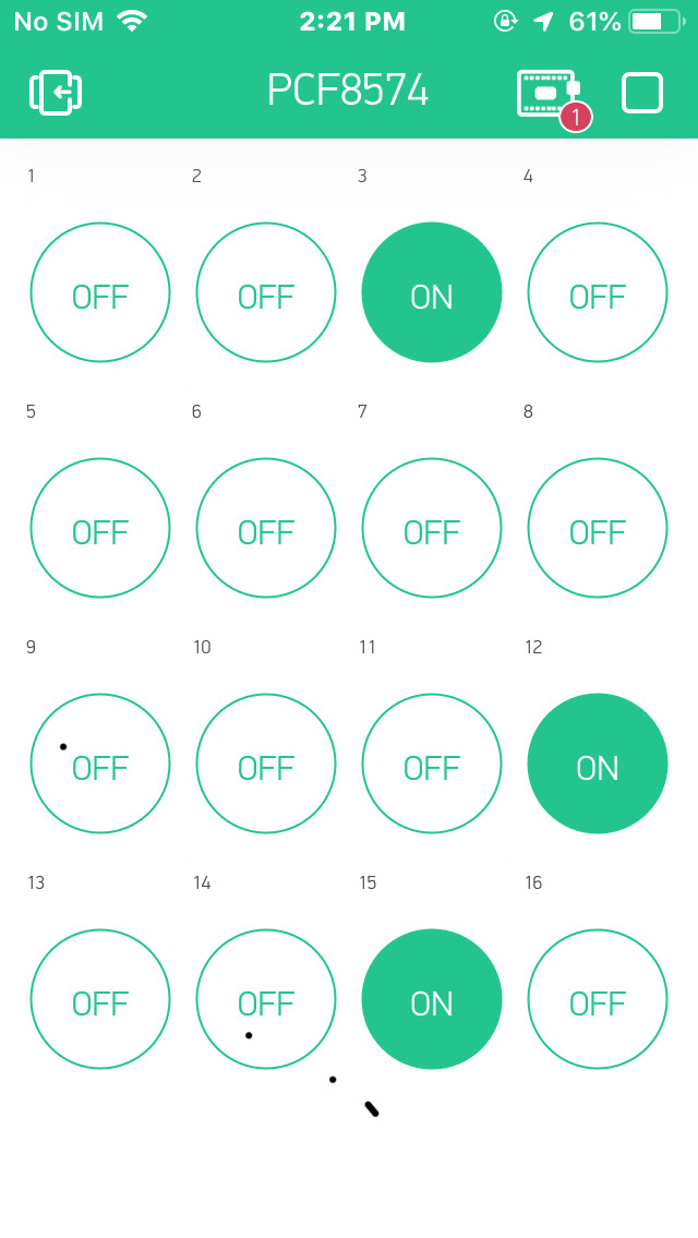
PCF8574 Controller Project for ESP32 and ESP8266
PCF8574 8-channel I2C Digital Input Output Expander, for ESP32/ESP8266 for ESP32/ESP8266, using Blynk
In the sample project, you can use these features:
- This example demontrates the use of a Master PCF8574 Controller (ESP32/ESP8266) to control 8 different PCF8574 Controllers running Blynk
- Each PCF8574 Controller can control 8 different relays, etc…
1 Like
WOW !! That’s interesting… But it doesn’t seem to have a manual control. Is it better to connect the button to the nodemcu or PCF8574 ??
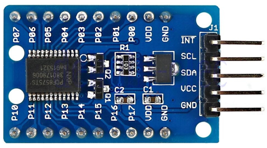
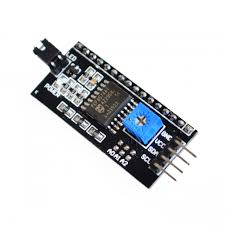
Here i am not able to get my hands on this IO expanders. I ordered online twice and the package was lost. I am able to get the once used with the i2c LCD display. This too uses the same PCF8574 ic . But it doesn’t work. I tried changing the address in the code but it did not work. Also soldered the pads for selecting the address. But works fine with the LCD display…
Did you run I2C scanner? Also with my nodes I have to use the default SDA and SCL pins as redefining the pins I’m the code dnt work.
I think that if you take a close look at the LCD serial backpack board that you have, you’ll see that the pins labelled D0, D1, D2 & D4 aren’t actually connected to anything - they don’t have any PCB traces connected to them and no connections to the pins on the PCF8574
This schematic confirms that:
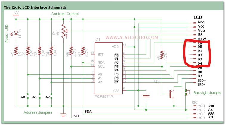
This means that at most you only have 4 outputs rather than 8. You could daisy-chain multiple ones together of course, up to 8 on one I2C bus, provided you gave each one a unique address.
The default address (with jumpers A0, A1 and A2 disconnected) is 0x27
More info here…
Pete.
1 Like
Yep, i tried scanning but it did not show any result on the serial monitor. So i dropped the idea of using this LCD i2c module as it is not ment to be used as IO expander.
I will try searching the IO Expander here locally. Let me see if i can find one.
For getting additional 4 outputs using this module is not worth the money…
There is another alternative, which is the CD74HC4067 chip. This is a 16 channel analogue/digital bi-directional multiplexer.
It doesn’t use I2C, and in my opinion is better suited to giving more output pins rather than as a way of providing more input pins, but as its output pins that you need then this might be worth cionsidering.
Pete.
I always face the problem while selecting pins for input and output on a nodemcu. As you know they all are not safe and some cannot be used too. And some spikes while booting. So i thought an IO Expander would solve this problem. It would be good if we use expander for both input and output. This way we need not worry about the pin selection on the nodemcu.
What do say on this ?
It depends what you want your project to do.
If you want a 16-way relay controller, as you originally said, then either device would be a suitable way of doing this. The I2C approach needs only 2 pins, the CD74HC4067 needs 4 pins. The NodeMCU has only 2 pins that don’t oscillate at boot-up, but in reality I don’t think that you’d have a problem with using either type of multiplexor for your relays when using a NodeMCU.
As far as inputs are concerned, this is where it gets a little more complex, but once again it depends what you want to do.
If you wanted 16 physical push-buttons, one for each relay, and maybe an additional push button that turned all 16 relays on or off then the problem is knowing when one of these buttons has been pressed.
Buttons connected directly to the board can have interrupts attached to them, to trigger a function in your code when the button is pressed. The alternative is to poll the button on a regular basis to see if it’s state has changed. If you only polled a button once every second then it would seem very unresponsive, but polling it more frequently increases the work that has to be done within the code, which can ultimately lead to problems with Blynk when you add more buttons.
I don’t think you can use interrupts with the CD74HC4067, but I might be wrong. If you cant, then it’s a case of polling each of the 16 inputs in sequence to see if a button has been processed. As each of the 16 inputs has to be selected by doing a digital write to one or more of the four controller pins (this may be done in the background, if you use a library, but it still needs to be done) then the process of polling the 16 buttons in turn will have a much higher overhead than polling 16 pins in sequence.
The I2C expander does have an interrupt facility, 8n fact some have two interrupts, one for each bank of 8 pins. I have no idea how these work though. Hopefully when an interrupt is triggered you’ll be able to read the 12C bus and see which pin was pressed, but I won’t know that until mine arrive and I do some experimentation.
With outputs you don’t have this problem. If you want to turn a relay on/off because a set of criteria are met in your code, or because you use a Blynk widget to signal that you want a relay activating or deactivating then it’s simply a case of sending the correct command.
Pete.
2 Likes
Thank you so much for the detailed reply !! My idea is just to add a push button and a relay to the IO expander. I dont need 16 relays. But 4 inputs and 4 outputs. And i should be able to read the button via i2c. But as you said interrupts cannot be attached on the i2c lines to detect the changes.
But instead we can add the push buttons to the nodemcu and attach the relays to IO expander. So booting oscillations doesn’t flicker the relays !
No, that’s not what I said. The I2C expanders do have an interrupt line (or two in some versions) that can be connected to a pin (or pins) on the NodeMCU. I just don’t know how you then determine which button triggered the interrupt, but I assume that there must be a way, otherwise there’s no point in having it.
I don’t think the other type of multiplexers support interrupts, but I might be wrong.
If you don’t want to control 16 relays as you originally stated then an ESP32 would be the simplest, cheapest and easiest to obtain solution and it has at least 14 pins that are suitable for input or output and another 4 pins that are input only.
Pete.
1 Like
Yeah ESP32 have more pins considering ESP12E. But i have never worked on ESP32. But i have one. I should start working on it.
The ESP12E is basically the same as a NodeMCU but without all the voltage regulator and USB interfacing circuitry, so won’t help.
This is a great reference for the ESP32 board, but make sure you have a good pinout diagram for your actual board, as not all pins are broken-out on all dev boards:
Pete.
1 Like