My Garage Door Opener

Hello everyone.

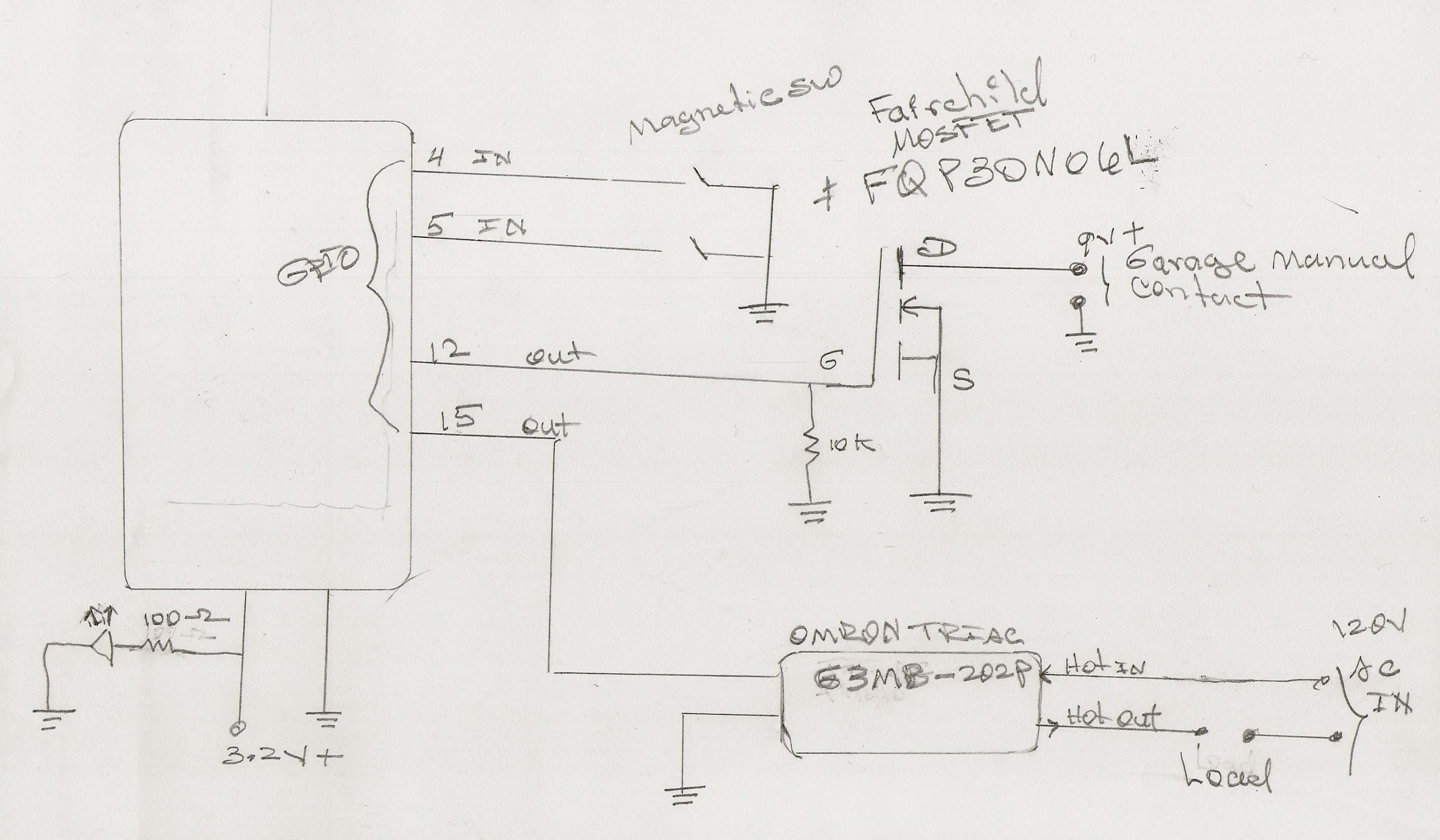
Here is my Garage Door Opener project. Yeap! Another Garage Door project. What the heck! I am attaching a manual sketch that I drew very quick so anyone can have an idea what I am talking about, plus some pics, and of course, my code. The sketch looks simple and so does the code, what is time consuming is the debugging process, testing, etc.

So here it’s more or less how it works:

GPIO 4 is the input(configure using the INPUT_PULLUP, so no external resistor needed. The internal resistor of the ESP8266 works very well) for a magnetic switch attached to garage door, when the door is open or close, Blynk notifies me, basically that is the only purpose of this switch, but very important to know if the door is open or close. More than once I’ve left the door open for so long, once was the whole night. No good.

GPIO 5 is the input(Same concept here, INPUTL_PULLUP is in action) of the magnetic switch that monitor but also commands to turn ON and OFF the lights in the attic. Blynk notifies me by email is this door has been opened. In my case, this is important .

GPIO 12 is the output that opens and closes the garage door. This pin is connected to a Fairchild MOSFET part number: FQP30N06L, when the Widget Button is pressed using virtual pin # 7, the MOSFET closes the circuit, so the door is open or close. Basically the MOSFET simulate the manual switch, actually the MOSFET Gate and Ground is connected in parallel with the manual sw. What is nice about this is that I can open the garage door two blocks away before I reach home, I love it! The 10K ohms resistor pulls the MOSFET gate to ground, so no false opening or closing if the main power goes off.

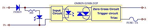
GPIO 15 is the output that turns ON and OFF the Attic’s lights when the door is open or close. This pin is connected to an OMRON TRIAC part # G3MB-202P. This TRIAC is 3.2V friendly. Pay attention to the HOT IN and HOT OUT, the load is connected between the HOT OUT and the Neutral wire of the 120V AC. This TRIAC don’t handle too much power, in my case is just about right.

An LED connected to +3.2V using a 100 ohms resistor tells me if the power is up.

Finally, I used the Adafruit Feather HUZZAH with ESP8266 plus FeatherWing Prototyping Add-on .

/*   ********************************************************************************************
          Garage Door Opener  & Artic Light Control
          Author: Alex Rodriguez / Los Angeles, CA - USA
          Reviewed: Feb. 21, 2016
 *   ********************************************************************************************
*/

#include <ESP8266WiFi.h>
#include <BlynkSimpleEsp8266.h>
#include <Wire.h>
WidgetLED led1(V6);
WidgetLED led2(V9);
WidgetLCD lcd(V10);
int inPinVal ; // Virtual Pin Input
char auth[] = "blink token here";

void setup()
{
  pinMode(4, INPUT_PULLUP);  // Garage Door Magnetic Sensor
  pinMode(5, INPUT_PULLUP);  // Attic Lights Magnetic Sensor
  pinMode(12, OUTPUT);       // Pin Connected to the MOSFET's Gate, and a 10K pulldown(gate to ground) Resistor
  pinMode(15, OUTPUT);       // Pin connected to the TRIAC
  Serial.begin(115200);
  Blynk.begin(auth, "SSID", "password");
}

// ---------[ Widget Button using  virtual pin # 7 ]--------------------

BLYNK_WRITE(V7) 
{
  if (param.asInt() == 0) 
  {   
   digitalWrite(12, LOW); //GPIO12
  } 
  else 
  {
  digitalWrite(12, HIGH); // GPIO12
  }
}

// =================={ Virtual LEDs Garage Magnetic SW Monitoring }=========
void checkPin()
{
  if (digitalRead(4)) // GPIO4
  {
    led1.off();
    led2.off();

  } else {
    led1.on();
    led2.on();
  }
}

// ========{ Garage Magnetic SW Monitoring Input }==================
void garageMagSensor ()
{
  int garageSensorSW = digitalRead(4); // GPIO4
  if (garageSensorSW == LOW)
  {
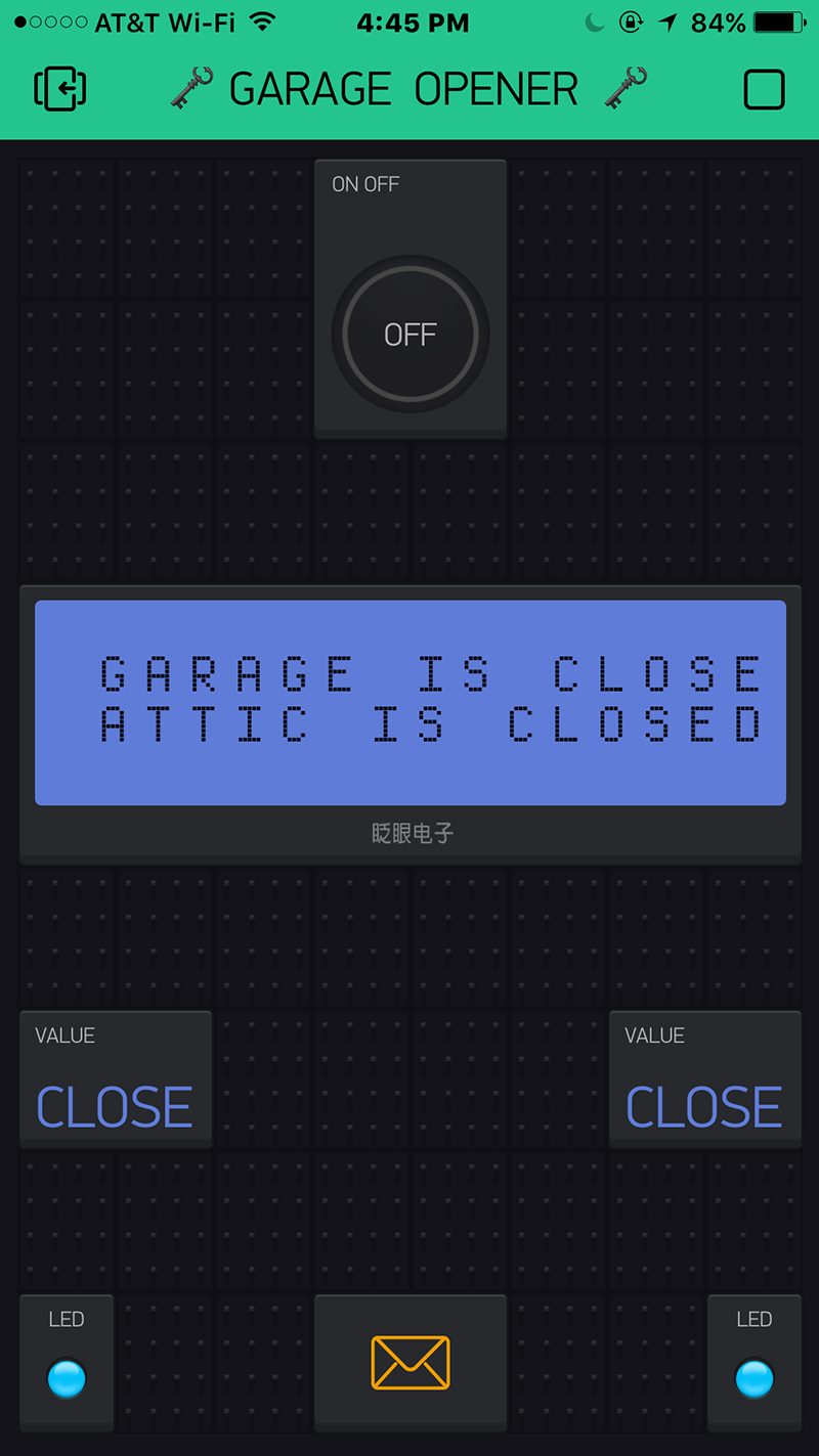
    Blynk.virtualWrite(0, "CLOSE"); 
    Blynk.virtualWrite(1, "CLOSE"); 
    lcd.print(1, 0, "GARAGE IS CLOSED"); // LCD print, column 1, row 0.
  }
  else
  {
    Blynk.virtualWrite(0, "OPEN"); 
    Blynk.virtualWrite(1, "OPEN"); 
    lcd.print(1, 0, "GARAGE IS OPEN"); // LCD print, column 1, row 0

  }
}

// ====================={ Attic Light Magnetic } =================================
void  atticMagSensor()
{
  int lightSensor  = digitalRead(5); // Attic Magnetic Switch connected to GPIO5
  if (lightSensor == LOW)
  {
    digitalWrite(15, LOW); // GPIO15
    Blynk.virtualWrite(2, "CLOSE"); 
    Blynk.virtualWrite(3, "CLOSE"); 
    lcd.print(1, 1, "ATTIC IS CLOSED"); // LCD print, column 1, row 1

  }
  else
  {
    digitalWrite(15, HIGH); // GPIO15
    Blynk.virtualWrite(2, "OPEN"); 
    Blynk.virtualWrite(3, "OPEN"); 
    lcd.print(1, 1, "ATTIC IS OPEN"); // LCD print, column 1, row 1
    Blynk.email("myname@yahoo.com", "ATTIC DOOR OPEN!", "Attic door has been opened.");
  }
}

// ==============( Void Loop  ) ====================================

void loop()
{
  garageMagSensor();
  checkPin();
  atticMagSensor();
  Blynk.run();
 yield();
}


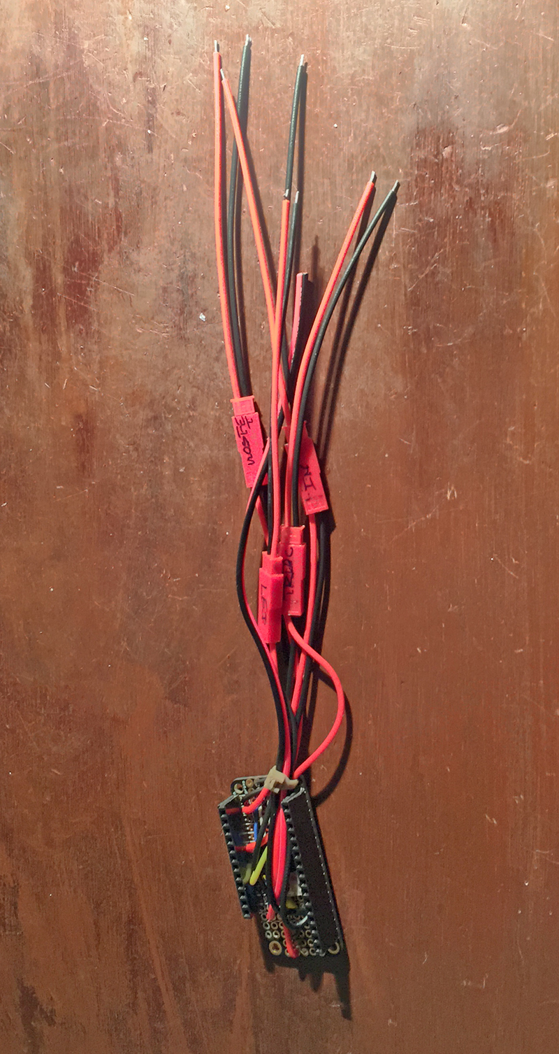
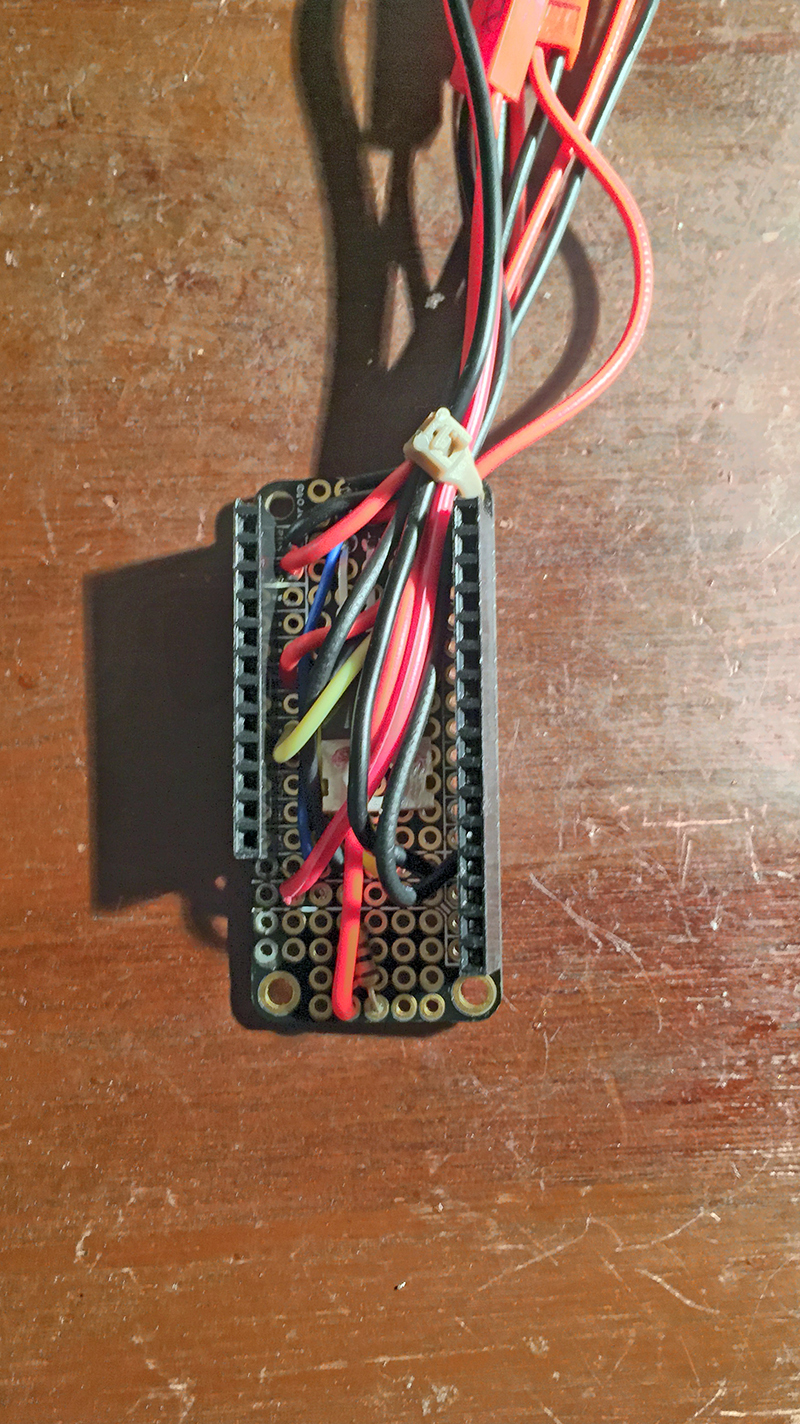
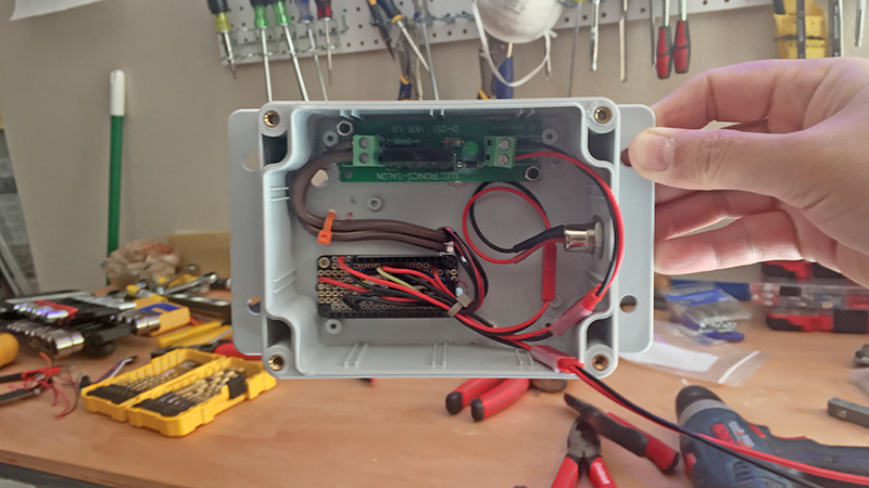
The Adafruit Feather HUZZAH with ESP8266 is not shown here. Basically, all the wiring is done using the Prototyping Add-on, so if the ESP8266 needs to be reprogrammed, just pull it out very easy.

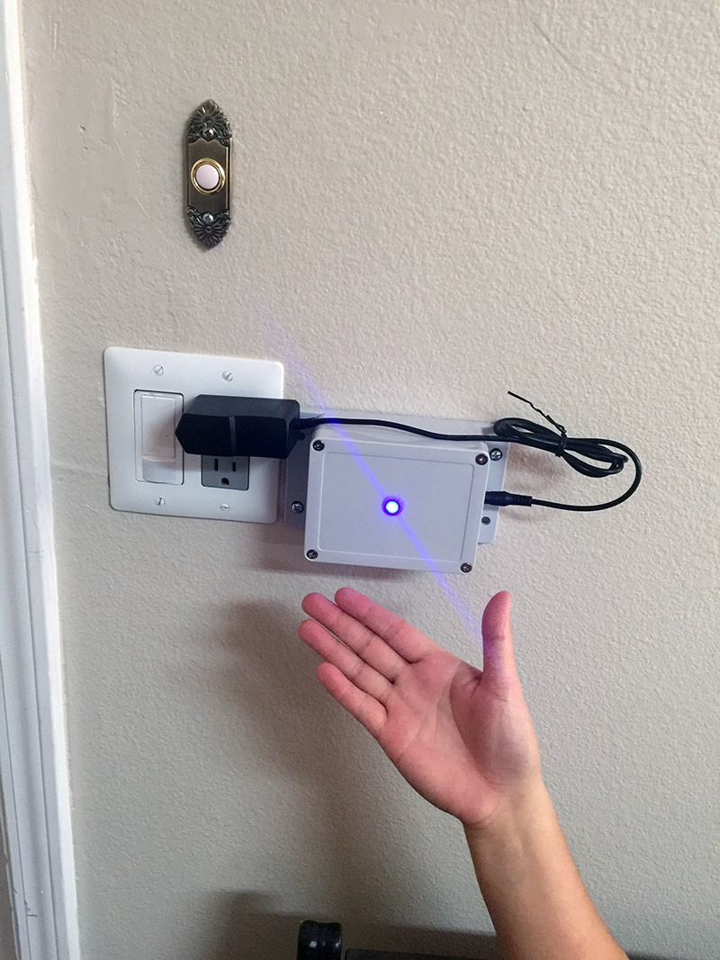
There you have it. All wires routed through the wall for a clean installation.

9 Likes

Congrats with great project, event it is garage opener :smile:. Could you please use “Preformatted text” icon so your code was more readable? Thanks.

Dmitriy:

I tried to use the pre-formated text, but I cannot get it working. If I correct, I place the text between this: </>, correct? I know the code will look way much better.

Ok. Did that for you :wink:

@ITAlex I see you are using Blynk.run 3 times in a loop. Why is that? I think you may remove 2 of 3 without any problems.

Also I see you are constantly sending data in loop to server. I wonder how it is working… Usually such code causes Flood error.

This pseudo code should be better :

bool current = 0; //logical placeholder - current status of the garage
bool previous = 1; //logical placeholder - previous status of the garage 

void doorOpen() {
        digitalWrite(15, HIGH); // GPIO15
        Blynk.virtualWrite(2, "OPEN"); 
        Blynk.virtualWrite(3, "OPEN"); 
        lcd.print(1, 1, "ATTIC IS OPEN"); // LCD print, column 1, row 1
        Blynk.email("myname@yahoo.com", "ATTIC DOOR OPEN!", "Attic door has been opened.");
}

void doorClose() {
        digitalWrite(15, LOW); // GPIO15
        Blynk.virtualWrite(2, "CLOSE"); 
        Blynk.virtualWrite(3, "CLOSE"); 
        lcd.print(1, 1, "ATTIC IS CLOSED"); // LCD print, column 1, row 1
}

void  atticMagSensor()
{
      current = digitalRead(5); // Attic Magnetic Switch connected to GPIO5
      if (current != previous) { //only run if there is a status change from previous state
           previous = current;   //reinitialize
           if (current == LOW)
          {
              doorClose() 
          }
          else
         {
               doorOpen();
         }
     }
}

void loop()
{
  Blynk.run();
  atticMagSensor();
}

Thanks for the advice, Dmitriy, I need to check the code later this week, the original code has only one Blynk.run(); inside the loop, we just added a yield(); inside the loop. It seems to be working fine.

You guys are so great, on top of providing Blynk which there nothing close to it out there, you guys also provide tips and tricks how to improve our codes.

Great job! I think the more garage door openers - the better! :smile:

Thanks for posting such a detailed description!

if it is that important, are you sure you trust email?

maybe add blynk.tweet too?

in your hardware - it is hard to tell, but where are your fuses?

Hello Pavel,

Agree with you, the more “garage door openers” , well more ideas I hope. You know, Blynk is fun, creatives, encourages me to do things. When I saw the first time that I can control the famous “hello world” or blink(an LED) Blynk…using my iPhone, bingo! The light turned on in my head, and some ideas came to my mind.

Right now I am working on a thermostat. Why re-inventing the wheel, you may ask. Well, here is the my dilemma. Most thermostat do not have a feature called: dead band zone and very few manufacturer implemented it , so I am working on one but implementing the “dead band zone.” The electronic part is a peace of cake for me, what is challenging sometimes is the programming part. Hey! no pain no gain, right? I know there is more than one way to skin a cat, and that is when the fun part starts. Please do not get me wrong, I love the kitties :slight_smile:

I have said it before, there is nothing out there compare to Blynk. You guys have done such a great job that whenever you guys decided to charge some amount, I am ready to support Blynk.

Thanks a lot!

1 Like

Hello Dave1829,

Thanks for the tip about tweet. I’ll check it out. mmmmm I guess I trust the email now. I forgot to mentioned about the fuse, and you have a valid question. The fuse is located inside the board that contains the TRIAC,is a tiny in-line little fuse. That is why I mention to pay attention to the HOT IN because you connect the HOT IN to the input where this fuse is located, the HOT OUT is after the fuse, is something goes wrong after the fuse, hopefully, it will open the circuit intermediately.
Here is a drawing of the TRIAC I am using. The A/B do not make too much sense to me. B should be labeled Hot IN, that is where the fuse is located, and A the Hot OUT, but they should be reversed.

Thank you, Dmitriy, for formatting the code for me. I have the new code that I want to post, but… How do I format it? I click the </> , and it says hit 4 spaces then paste the code?

Once again, Thank you for your time.

Just select your code and press </>.

nice project.
and in the plastic box, it looks very professional, good work!

Thank you, Gustavo. My pleasure to share ideas.

please also help me

Hi,
Could someone help me with this issue I am facing:

I have 2 ESPs, one controlling the gate and the other with a magnetic switch to tell me whether the gate is open or closed. It works fine when I am at home connected to wifi or when I am outside connected to 3g.

However, when I activate close gate and drive off, even though the gate closes, the LCD still shows gate is open. I think this is due to the transition from wifi to 3g and somehow, the LCD did not update the status. If I close the app and open the app, it will show the gate as closed. Is there something I can do to ensure the LCD gets updated correctly? Thanks.

Code for magnetic switch

// The purpose of this sketch is to make use of a proximity sensor to indicate on the 
// Blynk app LCD widget whether the Gate is open or close.


#define BLYNK_PRINT Serial    // Comment this out to disable prints and save space
#include <ESP8266WiFi.h>
#include <BlynkSimpleEsp8266.h>
#include <SimpleTimer.h>
#include <BlynkWidgets.h>
#include <WidgetLCD.h>
SimpleTimer waitTimer; // Name the SimpleTimer waitTime
WidgetLCD lcd(V12); //

 int sensorPin=12; // assign widget LCD to tie with gpio pin 12


// You should get Auth Token in the Blynk App.
// Go to the Project Settings (nut icon).
char auth[] ="xxxxxxxxxxxxxxxxxxxxxxxxx"; 

// ====================================================== 

void setup()
{
  pinMode (sensorPin,INPUT); // assign sensorPin as input

  pinMode(sensorPin, INPUT_PULLUP); // use ESP12 internal resistor to pullup sensor pin high i.e. 3V

  lcd.clear(); // clear LCD widget
  
  Serial.begin(115200);
  Blynk.begin(auth, "xxxxxxxxxxxx", "xxxxxxxxxxxx");
}

void loop()
{
   Blynk.run();
  
   sensorCheck(); // run sub-routine to check status of proximity sensor
       }
   
 // sub-routine to check status of proximity sensor

 void sensorCheck() // sub-routine to check sensor status
 
 { 
 int sensorValue = digitalRead(sensorPin);  // read the sensor pin and assign sensorValue to it.
  if (sensorValue==HIGH){  // if value is HIGH, display GATE OPEN on LCD
    lcd.print(2,0,"GATE IS OPEN");  // print starts at column 2, row 0 or 1st row. 2 rows in total
    } 
     else {
          lcd.print(2,0,"Gate Closed ");} // if value is LOW, display Gate Closed on LCD
                                          // the magnetic switch is wired such that when in contact, it pulls the sensor
                                          // pin low.
                                  
   
 }

Code for button

#define BLYNK_PRINT Serial    // Comment this out to disable prints and save space
#include <ESP8266WiFi.h>
#include <BlynkSimpleEsp8266.h>

// You should get Auth Token in the Blynk App.
// Go to the Project Settings (nut icon).
char auth[] ="xxxxxxxxxxxxxxxxxxxxxxxx";

int ledPin4=4; // assign widget LED to tie with gpio pin 4

int ledPin5=5; // assign widget LED to tie with gpio pin 5

// ====================================================== 

void setup()
{
  
  Serial.begin(115200);
  Blynk.begin(auth, "xxxxxxxxxxxxx", "xxxxxxxxxxxxxxxxxxxxx");
 
pinMode (ledPin4,OUTPUT); // assign ledPin4 as output
pinMode (ledPin5,OUTPUT); // assign ledPin5 as output

}


void loop()
{
   Blynk.run();
   
  int led4value = digitalRead (ledPin4);  // note digitalRead used although this is output pin.
  if (led4value==HIGH){  // if value is HIGH, turn ON virtual LED 4
    Blynk.virtualWrite (ledPin4,HIGH);  // note syntax is Blynk.virtualWrite
    } 
     else {
      Blynk.virtualWrite (ledPin4,LOW);
     }

 int led5value = digitalRead (ledPin5);  // note digitalRead used although this is output pin.
  if (led5value==HIGH){  // if value is HIGH, turn ON virtual LED 5
    Blynk.virtualWrite (ledPin5,HIGH);  // note syntax is Blynk.virtualWrite
    } 
     else {
      Blynk.virtualWrite (ledPin5,LOW);
     }

     
    }

It really doesn’t look like you have followed the Blynk example sketches very well, make sure you implement Blynk according to the examples…

And you shouldn’t cross-post… :confused:

Anyone with garage door opener facing this problem?

Developers, is there a line I can add in the code to refresh the app to solve this problem?

Thanks!

Did you find the Blynk.syncAll code?