Okay @Bill_Donnelly, here’s something for you to get your teeth into…
Some thoughts, code and testing methodology on the wind speed sensor (anemometer)…
The sensor I use was popularised by Maplin, which was a UK High Street and mail order electronics company that went bankrupt 2018. They sold a range of weather stations and spare parts (at surprisingly low prices, which was uncommon for Maplin). These products obviously weren’t manufactured by, or exclusively for, Maplin; so are used in a variety of other weather stations and are readily available online. Although Maplin re-launched itself as an online-only retailer in 2019, they no longer seem to sell weather stations or spare parts.
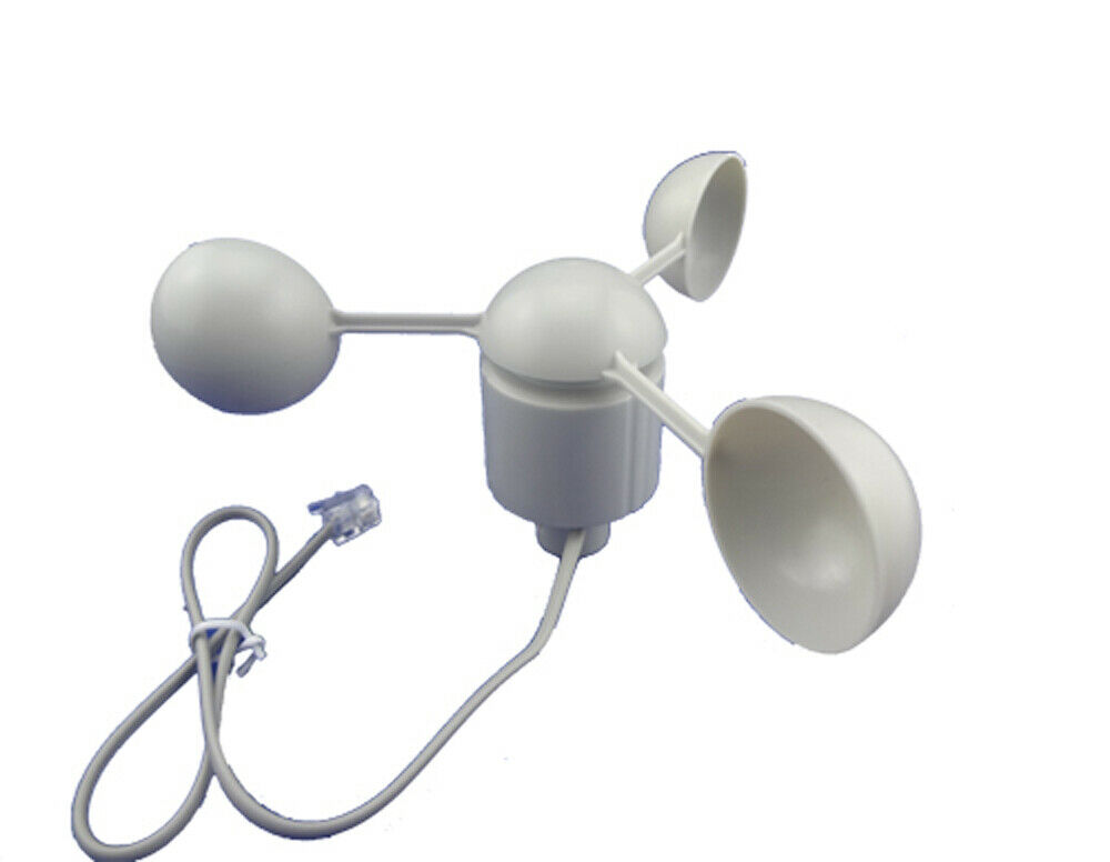
The sensor has three cups, one magnet and one reed switch. The slightly unexpected thing is that the reed switch is actuated twice per revolution.
Calculating the wind speed
There is a lot of misinformation on the internet about how to interpret/calibrate the data coming from the sensor. The two phrases that are used a lot are:
“A wind speed of 2.4 Km / hr causes a rotation of one per second” and “A wind speed of 1.492 Mph (2.4 km/h) causes the switch to close once per second”.
Clearly these statements cannot both be true, unless there is a version of the sensor which only provides one pulse per revolution (which seems highly unlikely, as people would be complaining that their wind speed was half or double what it should be when they fitted a replacement sensor).
I’ve discovered (by testing alongside a hand-held digital anemometer) that one pulse (half a revolution of the anemometer) per second represents a wind speed of 2.4 km/h (1.492 Mph) . As I’m British I still think in Mph, so I multiply the number of pulses in a measurement period by 1492 then divide by the number of millis in the measurement period. Here is an example to prove the maths…
1 pulse per second = 1.492 Mph so 10 pulses per second = 14.92 Mph
10 pulses per second over a 5 second period = 50 pulses over a 5000ms period
50 * 1492 / 5000 = 14.92 Mph
I’m using a 5 second measurement period as it smooths out the readings at low rotational speeds and reduces the number of times that the function which calculates the windspeed is called. All Interrupts have to be halted while these calculations are being done to ensure that the calculation isn’t interrupted (see what I did there  ), so the less frequently this calculation is done the less data will be missed from the sensors. Bear in mind that if you are also using interrupts for a tipping bucket rain gauge then these interrupts will also be ignored while the wind speed calculation is being performed (and vice-versa when rainfall is being calculated).
Presumably, once Blynk is introduced into the equation these functions are where you’ll be pushing the data to Blynk, which all takes time.
By the way, I don’t use interrupts on the wind direction vane, I simply have it connected to the analogue pin on my Wemos and read the value every 5 seconds then calculate the wind direction from this.
So, my current code is structured so that it calculates the windspeed, rainfall and current wind direction in one function that is called every 5 seconds. Whether this proves to be my long term solution is yet to be decided.
Debouncing the contacts
The contacts of the reed switch create a bit of noise when they open and close, so without some debouncing it’s easy to get three or four pulses per rotation rather than just two. I connect the sensor to Gnd and a GPIO pin that is pulled high using the INPUT_PULLUP command in the pinMode declaration. This means that I look for falling edges to trigger the interrupts, so my interrupt is defined as FALLING.
The experimentation described in the next part is a bit hit and miss, because of the need for the interrupt service routine to be clean and quick to execute. When you start adding serial print statements to monitor the timing of the pulses from the reed switch, the process of measuring the action is affecting the results - Heisenberg’s Uncertainty Principle in action!
After using serial print statements to print the current millis() value each time an interrupt is triggered, I discovered that the unwanted ‘bounce’ pulses were happening within the same 1 millisecond period as the actual pulse. As a result, I switched to using micos() to analyse the timing. This is where things started to get a bit messy and, once I’d established some sort of range to experiment with, it was a case of trial and error. Eventually I settled on a debounce time of 250 microseconds. This more than enough to eliminate switch bounce on the sensor that I’m using, so I think it’s a good value to work with. However, I’ve since realised that it could be increased massively without any detrimental effect – see below.
I thought it was necessary to ensure that we don’t spend so much time waiting for the next pulse, so that real pulses aren’t missed at high wind speeds. For this reason I also ran my NodeMCU (a Wemos D1 Mini actually) at 160MHz rather than the standard 80MHz, as the processor has quite a bit of timing-critical work to do; especially when you factor-in other sensors that it’s dealing with and the Blynk operations that will be happening in the background.
I’ve not set-up any Blynk code in my test sketch, but I have used the Blynk BlynkSimpleEsp8266.h library to give me access to the BlynkTimer. As I said in a previous post, my weather station in Spain uses MQTT rather than Blynk, and although the hardware side of things is up and running the firmware still has lots of room for improvement.
I did some tests to ensure that a steady stream of pulses was still being delivered at high rotational speeds. These involved the use of blast of compressed air from my small workshop compressor, and I was able to record 47 pulses per second, which translates to a rotational speed of 2,820 RPM or 70.12 Mph (31.3 M/s or 112.8 km/h). As the compressor reservoir is quite small, I switched to timing over a one second period as the compressor was struggling to deliver the same pressure for 5 continuous seconds.
The 250 microseconds minimum time between pulses (as a result of the debouncing) means that the theoretical maximum is 4 pulses per millisecond, or 4,000 pulses per second. Maybe the use of micros() rather than millis() in the debounce routine was a bit of an overkill? There’s certainly scope to increase the debounce time without affecting the high speed readings too much.
Anyway, here’s my simple code that just monitors and calculates windspeed…
#include <BlynkSimpleEsp8266.h>

#define pin_anemometer 4                  // GPIO 4 = Pin D2 on NodeMCU
#define wind_speed_sample_period 5000     // How often we caluulate/print the windspeed (in milliseconds)

volatile int last_windspeed_interrupt;
volatile int num_interrupts;

float mph_float;
float m_sec_float;

BlynkTimer timer;


void IRAM_ATTR countAnemometer()
//=======================================================
// Interrupt handler for anemometer. Called each time the reed
// switch triggers (half of a revolution).
//=======================================================
{
  if(micros()-last_windspeed_interrupt>=250)  // Debounce for the reed switch in the anenometer, no two pulses within 250 micros of eachother
  {
    num_interrupts++;
  }

  last_windspeed_interrupt=micros();
}


void calcWindSpeed()
//=======================================================
// Calculate the wind speed, and display it.
// 1 interrupt pulse (half a revolution) per second = 1.492 mph
// = 0.6667 Metres Per Second
//=======================================================
{
  noInterrupts();
    mph_float=1492*num_interrupts;
    mph_float=mph_float/wind_speed_sample_period;

    m_sec_float=666*num_interrupts;
    m_sec_float=m_sec_float/wind_speed_sample_period;

    Serial.print("Sample period in milliseconds = ");
    Serial.println(wind_speed_sample_period);

    Serial.print("Number of interrupts = ");
    Serial.println(num_interrupts);

    Serial.print("Windspeed in MPH = ");
    Serial.println(mph_float);

    Serial.print("Windspeed in Metres/Sec = ");
    Serial.println(m_sec_float);
    Serial.println();

    num_interrupts = 0;        // Reset counter
  interrupts();
}


void setup()
{
  Serial.begin(74880);

  pinMode(pin_anemometer, INPUT_PULLUP);
  digitalWrite(pin_anemometer, HIGH);
  attachInterrupt(pin_anemometer, countAnemometer, FALLING);

  timer.setInterval(wind_speed_sample_period, calcWindSpeed);
}


void loop()
{
  timer.run();
}
Let me know if this gives more consistent results.
Also, be aware that the small hand-held wind speed meters can be affected by electrical noise, so placing one too close to the anemometer will give false (high) readings. Also, the anemometer isn’t at all sensitive to wind direction - it will rotate at the correct speed no matter which horizontal direction the wind strikes it from. The hand-held meters will only give an accurate reading if they are pointing directly into the wind, so it’s best to use the wind direction vane of your weather station as a guide to tell which direction to point the hand-held meter in.
Pete.