Hello,
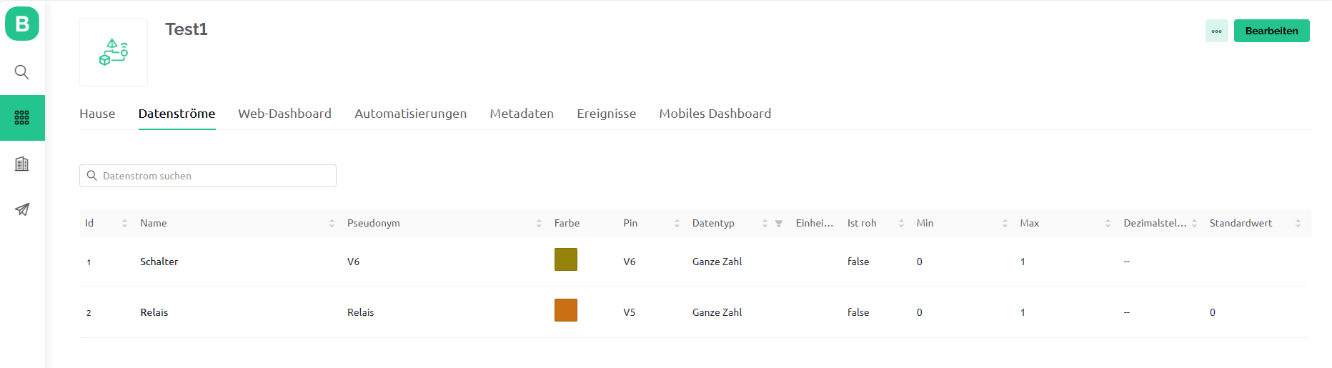
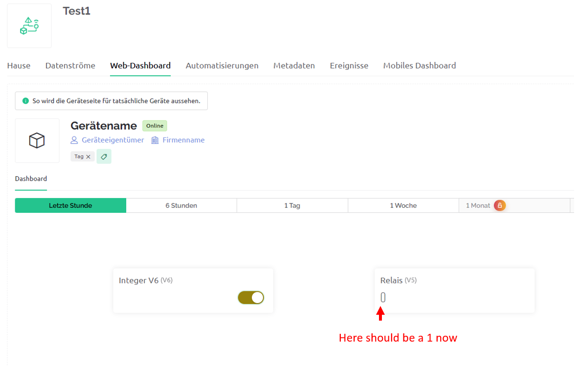
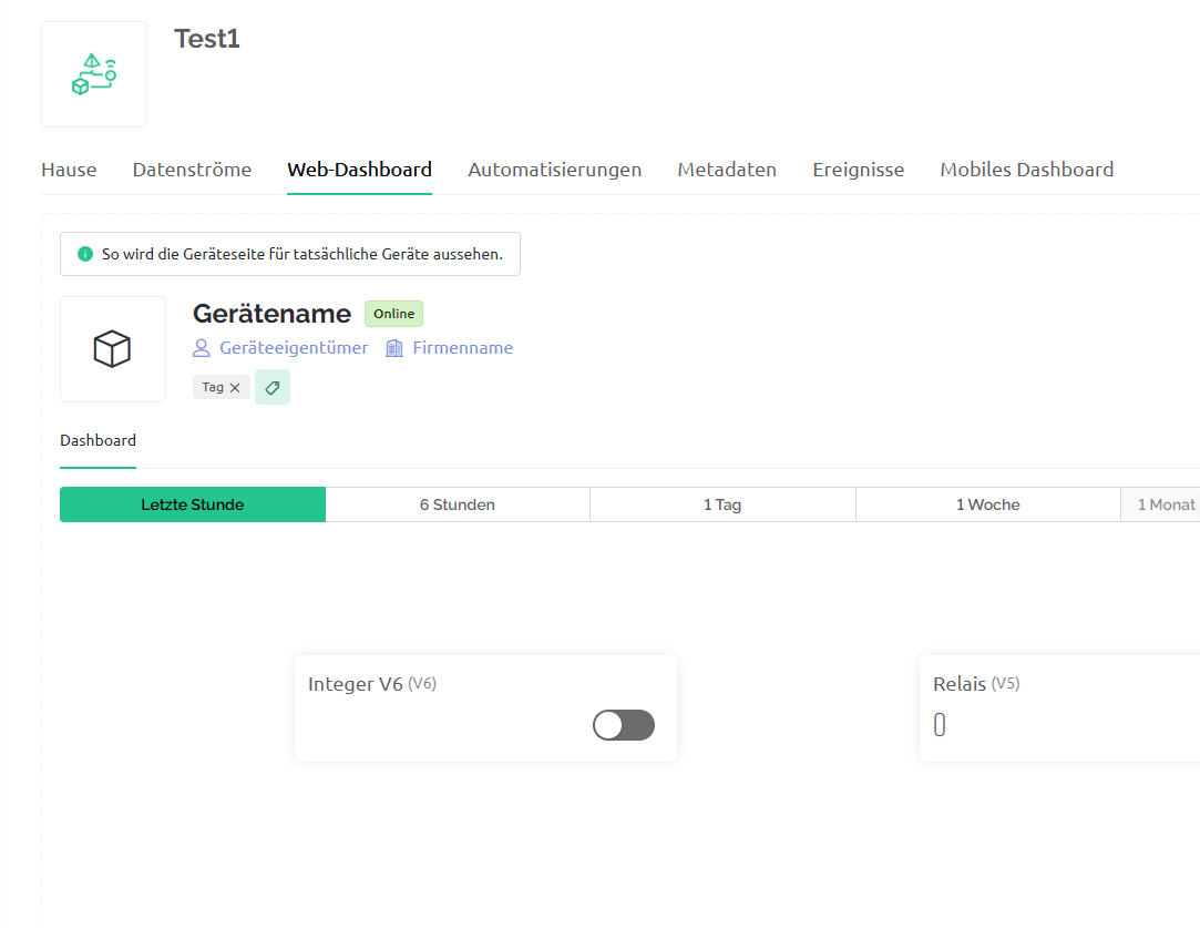
I want to switch a relay on and off with a switch on the web dashboard. I also want the dashboard to display whether the switch is On = 1 or Off = 0. The sketch is actually simple, but the device is always displayed offline.
I’m just not getting anywhere. Here is my sketch.
#define BLYNK_TEMPLATE_ID "TMPL47nwefFmL"
#define BLYNK_TEMPLATE_NAME "Test1"
#define BLYNK_AUTH_TOKEN "wQMHjmwdlnarAErSG7z_TgbfRULwpKYe"

#define BLYNK_PRINT Serial
#define RELAI 12
#include <ESP8266WiFi.h>
#include <BlynkSimpleEsp8266.h>

// Your WiFi credentials.
char ssid[] = "xxxxxxxxxxx";
char pass[] = "yyyyyyyyyy";

BLYNK_CONNECTED()
{
  Blynk.syncVirtual(V6);  // will cause BLYNK_WRITE(V6) to be executed
}
BLYNK_WRITE(V6) // Executes when the value of virtual pin V6 changes
{

  int wert = param.asInt();
  Blynk.virtualWrite(V5, wert);

  if(wert == 1)
  {
    // execute this code if the switch widget is now ON
    digitalWrite(RELAI,HIGH);  // Set digital pin 6 HIGH
  }
  else
  {
    // execute this code if the switch widget is now OFF
    digitalWrite(RELAI,LOW);  // Set digital pin 6 LOW
  }
}

void setup()
{
  // Debug console´
  Serial.begin(115200);
  pinMode(RELAI, OUTPUT);
  Blynk.begin(BLYNK_AUTH_TOKEN, ssid, pass);
 }


void loop()
{
  Blynk.run();
 }
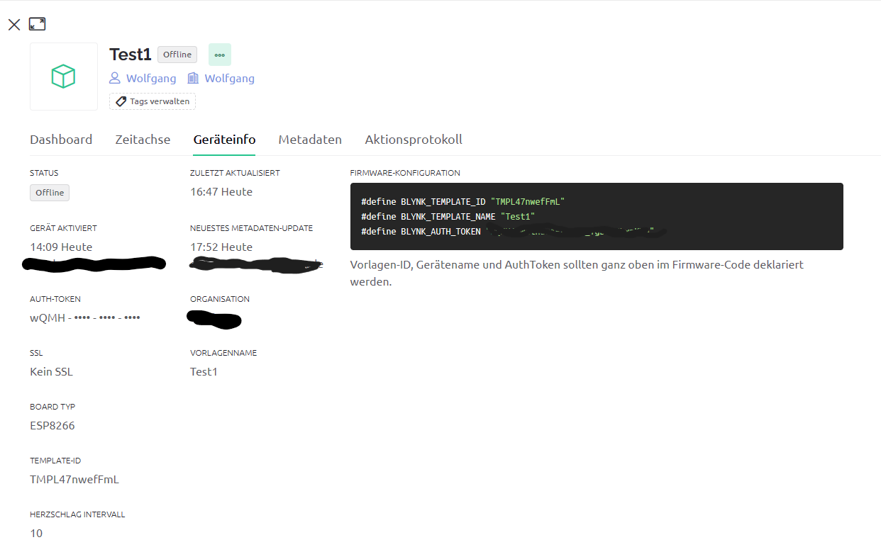
Your screenshot shows the desktop in template view, which is the design view. For the widgets to work you need to switch to Device view, which you access via the spyglass at the top left hand side of the screen.
Hello Pete,
thanks for the quick reply.
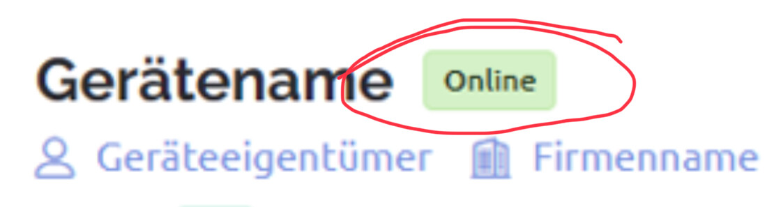
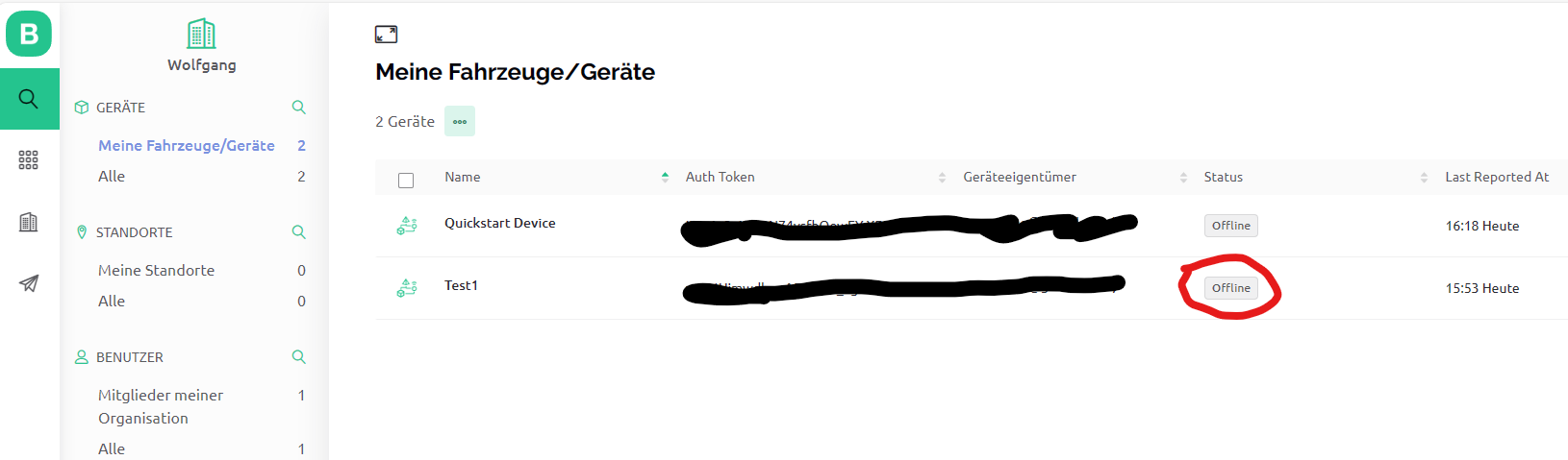
in the device view “offline” is displayed (see picture).
When I connect the ESP8266 with the sketch from the Quickstart, it shows me “online” immediately. Both sketches are almost the same.
@Oscar_24 Please edit your post, using the pencil icon at the bottom, and add triple backticks at the beginning and end of your code so that it displays correctly.
Triple backticks look like this:
```
Copy and paste these if you can’t find the correct symbol on your keyboard.
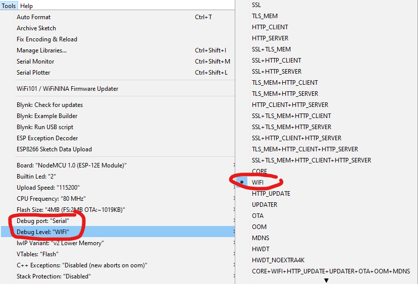
You’ve chosen a baud rate of 115200 for your serial debug output, and you clearly have your serial monitor set up the same baud rate.
The ESP8288 normally has a native baud rate of 74880, so it’s outputting its boot messages at this baud rate. As you have your serial monitor set to a different baud rate these system messages from the board appear as garbage.
You’d be better using 74880 as the baud rate for serial debug messages, so that you see both the board’s boot messages and your serial debug messages together, eith your serial monitor set to 74880.
Your message appears to show that your board is failing to connect to your WiFi network. Are your SSID and password correct (remember that both are case-sensitive) and are you attempting to connect to a 2.4GHz network? (ESPs don’t support 5GHz WiFi).
ok, I have changed the baud rate. Now I have the following output on the serial monitor:
 ets Jan  8 2013,rst cause:2, boot mode:(3,6)

load 0x4010f000, len 3424, room 16
tail 0
chksum 0x2e
load 0x3fff20b8, len 40, room 8
tail 0
chksum 0x2b
csum 0x2b
v00046700
~ld
rf cal sector: 1020
freq trace enable 0
rf[112] : 0�[89] Connecting to "my SSID"
The sketch from Quickstart also runs with the same device and go online, so the problem probably can’t be related to the frequency of the network. My SSID and password are correct, I copied and pasted and checked several times.
Re-compile the sketch and upload it, then take a look at your serial output to see what issues are being reported when attempting to connect to your WiFi.
I changed the settings in the IDE and got the following output in the serial monitor:
scandone
no "my SSID" found, reconnect after 1s
wifi evt: 1
STA disconnect: 201
reconnect
rf cal sector: 1020
freq trace enable 0
rf[112] : 0�
SDK:2.2.2-dev(38a443e)/Core:3.1.2=30102000/lwIP:STABLE-2_1_3_RELEASE/glue:1.2-65-g06164fb/BearSSL:b024386
[90] Connecting to "my SSID"
fpm close 1
mode : sta(ec:fa:bc:59:3d:be)
add if0
wifi evt: 8
scandone
no "my SSID" found, reconnect after 1s
wifi evt: 1
STA disconnect: 201
reconnect
scandone
no "my SSID" found, reconnect after 1s
My divice is always offline.
I compiled the sketch from the Quickstart (sketch name: firmware) with the same settings in the IDE. I also attach the output of the serial monitor.
This device is onlin.
The sketch is almost identical to the previous one. Only the query for the value of param.asInt() is inserted. I don’t understand why the sketch “firmware” runs online and the other sketch doesn’t.
To make any sense of the QuickStart sketch you need to change the baud rate to 74880.
For any of us to help you with the differences with the two sketches you will need to post both sketches, and include your un-redacted WiFi credentials.
Clearly your core debug output for your non-working sketch is reporting that it can’t find the SSID that you’re using, and that is where you need to focus your efforts.
/*************************************************************

  This is a simple demo of sending and receiving some data.
  Be sure to check out other examples!
 *************************************************************/

/* Fill-in information from Blynk Device Info here */
#define BLYNK_TEMPLATE_ID "TMPL44IqsjX1z"
#define BLYNK_TEMPLATE_NAME "Quickstart Template"
#define BLYNK_AUTH_TOKEN "xxxxxxxxxxxxxxxxxxxxxxxxxxx"

/* Comment this out to disable prints and save space */
#define BLYNK_PRINT Serial


#include <ESP8266WiFi.h>
#include <BlynkSimpleEsp8266.h>

// Your WiFi credentials.
// Set password to "" for open networks.
char ssid[] = "WLAN-wosi";
char pass[] = "xxxxxxxxxxxxxxx";

//BlynkTimer timer;

// This function is called every time the Virtual Pin 0 state changes
BLYNK_WRITE(V0)
{
  // Set incoming value from pin V0 to a variable
  int value = param.asInt();

  // Update state
  Blynk.virtualWrite(V1, value);

}

/* This function is called every time the device is connected to the Blynk.Cloud
BLYNK_CONNECTED()
{
  // Change Web Link Button message to "Congratulations!"
  Blynk.setProperty(V3, "offImageUrl", "https://static-image.nyc3.cdn.digitaloceanspaces.com/general/fte/congratulations.png");
  Blynk.setProperty(V3, "onImageUrl",  "https://static-image.nyc3.cdn.digitaloceanspaces.com/general/fte/congratulations_pressed.png");
  Blynk.setProperty(V3, "url", "https://docs.blynk.io/en/getting-started/what-do-i-need-to-blynk/how-quickstart-device-was-made");
}*/

// This function sends Arduino's uptime every second to Virtual Pin 2.
/*void myTimerEvent()
{
  // You can send any value at any time.
  // Please don't send more that 10 values per second.
  Blynk.virtualWrite(V2, millis() / 1000);
}*/

void setup()
{
  // Debug console
  Serial.begin(74880);


  Blynk.begin(BLYNK_AUTH_TOKEN, ssid, pass);

  // Setup a function to be called every second
 // timer.setInterval(1000L, myTimerEvent);
}

void loop()
{
  Blynk.run();
  //timer.run();
  // You can inject your own code or combine it with other sketches.
  // Check other examples on how to communicate with Blynk. Remember
  // to avoid delay() function!
}

This is the sketch
"test03_steuerung_Relais_2_0"

#define BLYNK_TEMPLATE_ID "TMPL47nwefFmL"
#define BLYNK_TEMPLATE_NAME "Test1"
#define BLYNK_AUTH_TOKEN "xxxxxxxxxxxxxxxxxxxxxxxxxx"

#define BLYNK_PRINT Serial
#define RELAI 12 // 12 bedeutet GPIO 12 und am NodMCU PIN D6

#include <ESP8266WiFi.h>
#include <BlynkSimpleEsp8266.h>

// Your WiFi credentials.
char ssid[] = "Wlan-wosi";
char pass[] = "xxxxxxxxxxxxxxxxxx";

BLYNK_WRITE(V6) // Executes when the value of virtual pin V6 changes
{
    int wert = param.asInt();
  Blynk.virtualWrite(V5, wert);
  if(wert == 1)
  {
    // execute this code if the switch widget is now ON
    digitalWrite(RELAI,HIGH);  // Set digital pin 6 HIGH
  }
  else
  {
    // execute this code if the switch widget is now OFF
    digitalWrite(RELAI,LOW);  // Set digital pin 6 LOW
  }
}

void setup()
{
  // Debug console´
  Serial.begin(74880);
  pinMode(RELAI, OUTPUT);
  Blynk.begin(BLYNK_AUTH_TOKEN, ssid, pass);
 }


void loop()
{
  Blynk.run();
 }

The wifi access data and the tokens are certainly entered correctly in the Sketch.
I have used the copy function in the Blynk.Console
The issue isn’t with the three lines of firmware data coming from the Blynk console. The sketch isn’t getting that far, because it can’t connect to your WiFi.
Have you copied these two lines of code from your working sketch…
and pasted them into your sketch that isn’t working?
Well, it’s clear from the debug output that there’s an issue with your device connecting to WiFi, so it’s not a Blynk issue.
Without seeing exactly what you’re doing, and how you’re doing it, it’s difficult to identify why you’re having this problem, so it’s difficult to help any further.
You should probably do all, the normal stuff like rebooting your router, double checking that your IDE settings are exactly the same for both sketches, re-checking your code, ensuring that the WiFi signal strength is good and that 5GHz networks have different SSIDs etc.
You could also modify your working sketch by adding-in your relay functionality to see if that approach works for you.
Hello Pete,
you surely know the quote:" the problem always sits in front of the device".
In this case it is completely true.
You rightly pointed out that it must be a problem with the WiFi connection. Although I checked the SSID and the password several times, I didn’t notice until just now that the SSID was written once in upper case and once in lower case. In my sketch with the relay the SSID was written in lower case. After the change the sketch runs now. Sometimes you can’t see the forest for the trees.
Thanks for your support.