I have two NodeMCU boards controlling 2 led strips in 2 different rooms. In order to save some space ajd to make it look cleaner in the Blynk app, instead of using 2 sets of sliders for controlling the colors, I used one set and the segmented switch widget, to control both led strips eith the sane sliders. One of them controls pins d1,d2,d3 while the other cintrols d5,d6,d7. In the segmented switch function, case 1, room=0 and case 2, room=1(0 for living room, 1 for bedroom). I’m using virtual pins for the sliders. What would be the easiest way to remember the sliders positions so when I change between rooms on the segmented switch widget, the sliders would go to the previous position?
As you can see, I choose one value for the living room an another fir the bedroom, the calue stays the same when I change back to living room, even tough the changes take effect only after touching the sliders
I would use virtual sync and virtual write in your segmented switch function.
Pseudo code:
living room -
r - v1
g - v2
b - v3
bedroom -
r - v4
g - v5
b - v6
slider values
r - v7
g - v8
b - v9
If segmented switch is set to living room
call virtual sync to get the value from the server for each r,g,b
use virtual write to set v7 to value of v1
use virtual write to set v8 to value of v2
use virtual write to set v9 to value of v3
If segmented switch is set to living room
call virtual sync to get the value from the server for each r,g,b
use virtual write to set v7 to value of v4
use virtual write to set v8 to value of v5
use virtual write to set v9 to value of v6
Edit: You many not need the virtual sync but it may be better to get the latest values?
I’ll post the code I’m using as soon as I get home. I have an idea about how to do it but I’d like to know if it’s prone to work as it’s kind of a hassle to get to the MCUs and upload the code. Also I’d like to specify that I use different codes for each mcu, None of the codes contain both led strips, they just work for ine led strip, I just changed the pins from d1,d2,d3 to d5,d6,d7, so nine of them contain all 6 digital pins, if that makes any sense
@JustBertC in that case, would I still need the ‘room’ variable? As I’ve seen you haven’t atributed any value to ‘room’ in the segmented switch function
//or does the variable receive the 1 and 2 values as in ‘case 1’ and ‘case 2’?
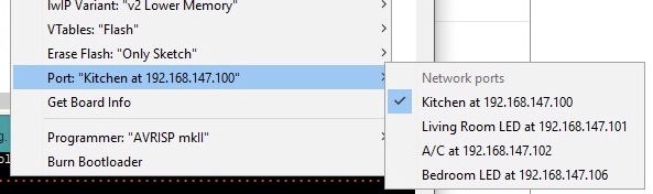
I’ve read more about OTA, seems like it is a nice thing to have as most of my circuits are mounted in cases that are hidden, and even tough they are powered by usb which would make it easy to upload the code, I use usb cables that don’t have data transfer… so each time I want to add a new code I ned to open up the case and so on.
Could I get more details about this process? How easy is it to implement to an already existing code? @PeteKnight if I’m not mistaken, I’ve read through one of your posts where you said there were about 3-4 lines of code (without using any serial print)
@dragos Yes there isn’t much to it. As you have said, no more than 10 lines (depending what you want to customise)
The biggest pain for me was python (well not technically python but my antivirus that closed all the ports to python - created an exception and it’s all wonderful now)
Read the link that @PeteKnight posted, that’s all I did - didn’t need to search anywhere else.
@dragos Personally I was a little confused by some of the code in that article. However the python setup worked as per the post. I will try to post my code here in a day or two.
So I’ve managed to make it work with the basicOTA sketch, I’m just not sure how to implement it to an already existing code. I’m currently trying this code and it seems to work: