Project created with esp8266 and 3 dht22, Blynk 2.0. And UTP CAT 5E Cable.
Dear All
I have an installation for temperature control in a pig farm. with three sensors and a noodemcu sp8266. The shorter distance sensors (10 and 30 meters) work perfectly, but the longer distance sensor (60 meters) sometimes gives erroneous readings, few lower. how can I do so that the signal does not have errors, I cannot change the cable that must be one of the factors that affects since it is not 100% copper. Is there a source that amplifies the signal so that it does not have loss for this distance or longer distances? If anyone knows and knows how to connect them I ask for help. thank you.
You’re probably better swapping to an I2C sensor like the SHT30.
Over long distances the issues will be voltage drop and cable capacitance. If you use the 5v rail rather than the 3.3v rail this will offset the voltage drop, but there’s nothing you can do about cable capacitance without swapping to different cable, preferably fully screened.
thanks pete
but I understand that although the DHT22 works with 5V the ESP8266 nodemcu only works with 3.3V on the data pins, and I know that if I feed the DHT22 with 5V I get 5V data. Due to those factory specifications, I never tried to avoid damaging the nodemcu. But if you tell me it works I’ll try.
I cannot change the quality of the cable, I am going to choose to move the nodemcu more to the middle to equalize distances. thank you
Can you provide documentation to confirm this? Although it may seem that you can get away with it, I don’t think the manufacturer’s absolute maximum ratings agree.
Not unless they back it up with updated datasheets or errata notices.
The datasheet version 6.9, last updated February 2023, in section 5.1 “Electrical Characteristics”, Table 5.1 states I/O VIH as maximum 3.6V
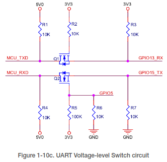
The Hardware Design Guidlines version 2.7, last updated February 2023, in section 1.4.7 “UART” they talk about the need for level shifters to convert 5V to 3.3V and they provide such a circuit in figure 1-10c. If GPIO pins (at least GPIO13_RX and GPIO15_TX) were 5V tolerant, this wouldn’t be required, so why go to the trouble of documenting it?
The IO of the ESP8266EX is a 3.3 V logic level. In the case of serial communication
with a 5 V CMOS logic system, a level switch circuit needs to be added externally.
See Figure 1-10c.
Looks like you’re going to be doing new cable runs then!
Seriously though, everyone does this and it works fine. The only time I’ve ever needed to use a level shifter was with when using an RFID reader that needs a power supply of 12v and outputs about 8v on its logic level pins. Even that didn’t kill the Wemos D1 Mini that I was using, but it couldn’t reliably read the data pulses from the RFID reader so a level shifter solved the problem.
I guess your other solution is to use three devices, each sending the data to Blynk independently, and locate these right next to the area you want to monitor. The problem you’re going to face then is amalgamating that data into a single display in Blynk, which is probably going to need you to use the REST API, but that’s not difficult.
Friends, I am going to tell you that I am going to change the cable for a 100% copper FTP, I am going to use the 5 volt power supply and I am going to move the device to the middle of the three sectors. I think that this is enough to avoid having more problems in this and future installations. Since we are here, I ask you another question, the same client has a freezer with merchandise that has to be stored at -50 degrees. for this reason I was looking for a more suitable sensor for these measurements and I bought two DS18B20 sensors. I never implemented these sensors with the nodemcu esp8266, I was looking for several codes from the forum and the internet but I can’t make them work, I need you to please send me a simple but infallible code to test them since I have doubts that they don’t work, so I return them and I buy from another supplier. I don’t know what’s wrong. or if they don’t walk thank you.
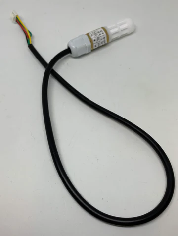
If you’re going to put any type of sensor in a freezer at -50 then you;re going to have to be careful with the sensor to ensure that it doesn’t suffer from ice damage. There is a waterproof version of the DS18B20 that is the one I’d choose.
As I said earlier, i wouldn’t use the DHT range of sensors for your humidity sensing application. They are inaccurate and slow, and difficult to use reliably in an industrial situation.
Moving to an I2C sensor such as the SHT range would be my preferred sensor and it may remove the need to replace your cabling.
I’ve been running a waterproof SHT30 in an outdoor weather station for a few years and it’s proven very reliable. That would be my choice of sensor for the pig farm environment that you’ve described.
If you are going to re-cable the current situation then I’d probably avoid a twisted pair cable, or at least do some tests first. If you do relocate your sensor to a central location then you could use multiple pairs bonded together for each sensor, which may help.
Dear Pete
I just tried this simple code, it links to wifi but it always gives me the same value, -127. I don’t know if I’m failing in something, I have to try with a resistor as I saw in the example between the power supply and the data pin. Any suggestions?
06:49:08.542 → La temperatura del sensor (index 0) is: -127.00
06:49:18.544 → Registrando temperaturas…DONE
06:49:18.544 → La temperatura del sensor (index 0) is: -127.00
06:49:28.528 → Registrando temperaturas…DONE
06:49:28.528 → La temperatura del sensor (index 0) is: -127.00
06:49:38.543 → Registrando temperaturas…DONE
06:49:38.543 → La temperatura del sensor (index 0) is: -127.00
And the Edgent thing, I use it because later it goes inside the project, to be able to update it remotely like my other devices through BlynkAir. In 2 days I receive the other sensors from the other provider, so I try again.And I comment you. Thank you.
You don’t need to use Edgent to be able to use Blynk.Air, but if you’re doing basic testing then I would have started with a non-Blynk sketch, then added-in a very basic Blynk sketch to ensure you can see the values in Blynk.
Yes Pete, I already tried with basic sketches, but the problem that I see is that it doesn’t even give me values on the serial monitor. I have updated the libraries and connected as I told you before. With this code it should work, or at least it would have worked in one of the 30 codes I tried before, among the forum ones, the chatgpt ones, etc…
I am inclined because it does not work, I have read in several places that there are clones of these sensors that work badly or do not work at all. We are going to make sure that I have the correct sensor, and then I start again with the tests, otherwise the times are shortened and I need to solve it as soon as possible. Thanks my friend.
I’ll post the code again as soon as I get the new sensor to work. (if I get it to work haha)
Yes… Arduino-Temperature-Control
I used several but I don’t know if they work well with esp8266. One called tester, another simple, and another Twopin. they all give me -127.
hello again, friend Pete, I’m telling you that I received the sensors from the new provider, but I get the same data, I have it connected to pin D1, I’ll give you the code, I’m using BlynkEdgent, but I think it has nothing to do with it, you Will you tell me, and if not please help me with a simpler way to test them.
#define BLYNK_TEMPLATE_ID "TMPL2p--Kt0FP"
#define BLYNK_DEVICE_NAME "CLIMAX MENOS5"


#define BLYNK_FIRMWARE_VERSION "0.1.0"

#define BLYNK_PRINT Serial
//#define BLYNK_DEBUG

#define APP_DEBUG

#define USE_NODE_MCU_BOARD

#include <OneWire.h>
#include <DallasTemperature.h>
#include "BlynkEdgent.h"

BlynkTimer timer;
#define ONE_WIRE_BUS D1  // Pin D1 para la conexión del sensor DS18B20
OneWire oneWire(ONE_WIRE_BUS);
DallasTemperature sensors(&oneWire);

void setup()
{
  Serial.begin(115200);
  delay(100);

  BlynkEdgent.begin();
  sensors.begin();

  timer.setInterval(10000L, sendSensor);
}

void sendSensor()
{
  sensors.requestTemperatures();
  float temp1 = sensors.getTempCByIndex(0);
  Serial.print("Temperatura: ");
  Serial.println(temp1);

  // Envía la temperatura a Blynk
  Blynk.virtualWrite(V1, temp1); // Cambia V1 al número de tu pin virtual en Blynk
}

void loop()
{
  BlynkEdgent.run();
  timer.run();
}
this is te serial monitor:

[46672] RESET_CONFIG => WAIT_CONFIG
[47477] AP SSID: Blynk CLIMAX MENOS5-E2D97
[47478] AP IP:   192.168.4.1
[47478] AP URL:  blynk.setup
[56706] WAIT_CONFIG => CONFIGURING
[125508] Applying configuration...
[125508] WiFi SSID: iPhone 12 Pass: 12345678
[125508] Blynk cloud: ChXW4ztRe5C9VGAaV2Nq3cYQAiIvN2qf @ blynk.cloud:443
[125512] CONFIGURING => SWITCH_TO_STA
Temperatura: -127.00
[126266] Switching to STA...
[127569] SWITCH_TO_STA => CONNECTING_NET
[127570] Connecting to WiFi: iPhone 12
[134038] Using Dynamic IP: 192.168.43.11
[134038] CONNECTING_NET => CONNECTING_CLOUD
Temperatura: -127.00
[135403] Current time: Thu Jun  1 23:10:14 2023
[135404] Connecting to blynk.cloud:443
[137718] Ready (ping: 12ms).
[138006] CONNECTING_CLOUD => RUNNING
[138038] Configuration stored to flash
Temperatura: -127.00
Temperatura: -127.00
Temperatura: -127.00
Temperatura: -127.00
Temperatura: -127.00
Temperatura: -127.00
Temperatura: -127.00
Temperatura: -127.00